

12V Battery Charge Indicator Circuit with LM324 IC
Monitoring the charge level of a battery is important for any DC-powered system, whether it’s part of a solar power setup, a UPS, or a portable device. Knowing when the battery is full or low can help prolong its life and ensure your equipment runs without unexpected shutdowns.
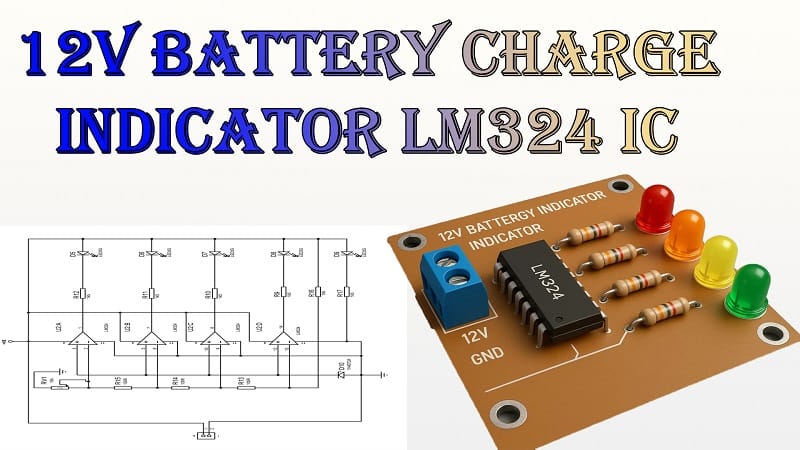
In this guide, we will build a 12V battery charge indicator circuit using the LM324 IC. The circuit uses LEDs to display the battery’s charge status, making it easy to check the voltage level at a glance.
How the Circuit Works
The LM324 IC contains four operational amplifiers (op-amps) in a single package. In this project, each op-amp acts as a voltage comparator. Comparators check the battery voltage against preset reference voltages. When the battery voltage exceeds a reference, the corresponding LED turns on.
The circuit uses five LEDs to indicate different charge levels. For example:
- LED 1: Very low charge (battery almost empty)
- LED 2: Low charge
- LED 3: Medium charge
- LED 4: Good charge level
- LED 5: Fully charged
The voltage thresholds are set using a combination of resistors, a 3V Zener diode, and a 10K trimpot for fine adjustment.
Materials for the Project
| S.No | Component Name | Specification / Value | Quantity |
| 1 | LM324 IC | Quad Operational Amplifier | 1 |
| 2 | LED | 5 mm (Red, Yellow, Green—as preferred) | 5 |
| 3 | Zener Diode | 3V, 0.5W | 1 |
| 4 | Trimpot (Preset) | 10KΩ | 1 |
| 5 | Resistor | 100Ω, 1/4W | 3 |
| 6 | Resistor | 1.5KΩ, 1/4W | 5 |
| 7 | Resistor | 10KΩ, 1/4W | 2 |
| 8 | Terminal Block (2-pin) | PCB mount | 2 |
| 9 | Perf Board | General-purpose PCB | 1 |
| 10 | Jumper Wires | Flexible / solid core | As required |
Download Circuit Diagram

(Here you would place your circuit diagram image for better clarity.)
The LM324 op-amps are wired as comparators. Each comparator gets two voltage inputs:
- Non-inverting input (+) – Connected to the battery through a voltage divider
- Inverting input (-)—Connected to the Zener diode reference voltage
When the voltage at the non-inverting input exceeds the reference, the op-amp output goes high, turning on the corresponding LED.
Step-by-Step Working Principle
1. Voltage Sensing
A voltage divider network made with resistors reduces the battery voltage to a safe range for the op-amps. This allows the LM324 to compare the battery voltage accurately without exceeding its input voltage limits.
2. Reference Voltage Generation
The 3V Zener diode and the 10K trimpot create a stable reference voltage for the comparators. By adjusting the trimpot, you can set the threshold levels for each LED.
3. Comparison
Each comparator in the LM324 compares the scaled battery voltage with a specific reference voltage.
- If the battery voltage is above the threshold, the output becomes high and lights up the LED.
- If it’s below the threshold, the LED remains off.
4. LED Indication
The LEDs are connected through 100Ω resistors to limit current and prevent damage. Each LED represents a different voltage level, so as the battery charges or discharges, the number of lit LEDs changes.
Voltage Threshold Settings
Here’s an example configuration for a 12V lead-acid battery:
| LED | Voltage Level | Battery Status |
| LED 1 | 10.5V or lower | Deep discharge (Recharge immediately) |
| LED 2 | 11.5V | Low charge |
| LED 3 | 12.0V | Medium charge |
| LED 4 | 12.5V | Good charge |
| LED 5 | 13.8V | Fully charged |
These values can be fine-tuned using the 10K trimpot to match your battery type and needs.
Assembly Instructions
Step 1 – Placing the Components
- Mount the LM324 IC on the perf board, leaving enough space for wiring.
- Place the LEDs in a row for a clear visual display.
- Install resistors, a Zener diode, and a trimpot according to the circuit diagram.
Step 2 – Making the Connections
- Connect the LEDs to the op-amp outputs through their current-limiting resistors.
- Wire the Zener diode and trimpot for the reference voltage line.
- Create the voltage divider network for the battery input.
- Use terminal blocks for easy connection to the battery.
Step 3 – Final Checks
- Double-check wiring against the circuit diagram.
- Ensure there are no short circuits.
- Verify correct polarity for LEDs and the Zener diode.
Step 4 – Testing the Circuit
- Connect the battery to the terminal block.
- Observe the LED indicators.
- Adjust the trimpot until the LEDs change at the desired voltage levels.
Applications
- Solar power systems—Monitor battery charge from solar panels.
- Portable battery packs—Get a quick visual charge status.
- UPS systems—Keep track of battery health.
- Automotive batteries – Check charging performance.
Advantages of Using LM324 for Battery Indicators
- Low power consumption—won’t drain the battery quickly.
- Wide operating voltage range—can work with most battery types.
- Four built-in comparators reduce the need for multiple ICs.
- Easy adjustability—fine-tuningssible via trimpot.
Tips for Better Accuracy
- Use precision resistors for voltage dividers.
- Keep wiring short to minimize noise pickup.
- Calibrate with a reliable digital multimeter.
- Ensure the battery is disconnected from charging sources during calibration for accuracy.
Final Thoughts
The 12V battery charge indicator circuit with LM324 IC is simple yet effective. It provides a quick, easy-to-read display of your battery’s charge status and can be adapted for different voltage ranges by adjusting resistor values and reference settings.
This project is a great addition to any battery-powered system, ensuring you always know when it’s time to charge or when the battery is at full capacity.