

This 4 channel GSM relay switch project using Arduino allows remote device control via SMS. The 4 channel GSM relay switch connects through a GSM module and relays to switch appliances on or off. Using this 4 channel GSM relay switch, you can automate devices anywhere. The 4 channel GSM relay switch uses Arduino, transistors, relays, and diodes. Build your own 4 channel GSM relay switch today.
Introduction
Home and industrial automation is becoming more common every day. Imagine being able to switch on your water pump, lights, or other appliances from anywhere in the world just by sending a text message. That’s exactly what we are going to build today: a 4 channel GSM relay switch using Arduino.
This project uses a GSM module to receive SMS commands, which are processed by an Arduino microcontroller. The Arduino then drives relays through transistors, turning connected devices ON or OFF. With 4 relays, you can independently control 4 devices.
This system is:
Reliable
Simple to build
Cost-effective
Easy to expand for more channels
Now, let’s walk through the complete design.

Materials for the Project
| Component | Quantity | Description | Buy Link |
|---|---|---|---|
| Arduino/Nano | 1 | Microcontroller board | Buy |
| GSM Module (SIM800/900) | 1 | For SMS communication | Buy |
| BC547 Transistors | 4 | NPN transistors for relay driving | Buy |
| 1kΩ Resistors | 4 | Base resistors | Buy |
| 5V Relays | 4 | Relay modules to switch loads | Buy |
| 1N4148 Diodes | 4 | Flyback protection diodes | Buy |
| Terminal Blocks | 4 | For connecting appliances | Buy |
| Jumper Wires | Several | For connections | Buy |
| Breadboard / PCB | 1 | For circuit assembly | Buy |
| 5V Power Supply | 1 | Regulated power for Arduino & relays | Buy |
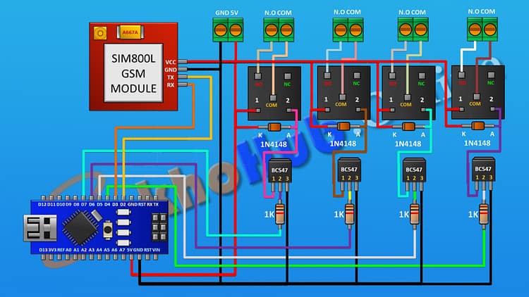
Circuit Diagram Explanation 4 Channel GSM Relay Switch
The heart of this project is the Arduino, which interfaces with the GSM module and controls 4 relays via BC547 transistors.
Power Supply
A regulated 5V power supply is used to power both Arduino and GSM module.
Relays also run from the same 5V source.
GSM Module to Arduino
TX (GSM) → D2 (Arduino)
RX (GSM) → D3 (Arduino)
VCC → 5V, GND → GND
Relay Driver Circuits (x4)
Each relay is controlled using a BC547 transistor as a switch.
A 1kΩ resistor limits current to the transistor base.
A 1N4148 diode across the relay coil prevents back-EMF damage.
The relay’s COM and NO terminals connect to the external appliance.
Arduino Control Pins
Relay 1 → D4
Relay 2 → D5
Relay 3 → D6
Relay 4 → D7
The circuit ensures that SMS commands received by GSM are interpreted by Arduino and mapped to relay ON/OFF signals.
Download Circuit Diagram
Step-by-Step Assembly Guide
Step 1: Arduino Setup
Place Arduino Nano or Uno on a breadboard.
Provide regulated 5V and GND connections.
Step 2: GSM Module Connection
Insert SIM card into the GSM module.
Connect TX → D2, RX → D3 using jumper wires.
Connect GSM module VCC → 5V, GND → Arduino GND.
Step 3: Relay Driver Circuit (First Channel)
Connect BC547 transistor emitter → GND.
Connect 1kΩ resistor from Arduino D4 → base of BC547.
Connect collector → one end of relay coil.
Other end of relay coil → 5V.
Place 1N4148 diode across relay coil (cathode → 5V, anode → collector).
Connect COM and NO terminals of relay to external load.
Step 4: Repeat for Remaining Channels
Relay 2 control pin: Arduino D5.
Relay 3 control pin: Arduino D6.
Relay 4 control pin: Arduino D7.
Each has its own transistor, resistor, diode, and relay.
Step 5: Testing
Upload Arduino code for GSM SMS reading and relay control.
Power the circuit.
Send SMS commands such as:
"ON1"→ Turns Relay 1 ON"OFF1"→ Turns Relay 1 OFF"ON2"→ Turns Relay 2 ON, etc.
Arduino Code
Step 6: Appliance Control
Connect household appliances like lights, fans, pumps, or motors to the relay output terminals.
Always use proper electrical safety precautions.
How It Works
When you send an SMS to the SIM card inserted in the GSM module, the module passes the message to Arduino.
Arduino checks the SMS string.
If the SMS matches a stored command (like “ON1”), Arduino sends a HIGH signal to the corresponding pin (D4).
The transistor switches on, activating the relay coil.
The relay contacts close, powering the connected appliance.
When you send “OFF1”, Arduino drives the transistor LOW, switching off the relay.
Advantages of GSM Relay Control
No internet required – works with basic GSM SMS.
Long distance control – anywhere the GSM network is available.
Multiple device control – 4 appliances in this project, expandable to more.
Secure operation – can be coded to accept SMS only from specific numbers.
Practical Applications
Controlling water pumps in agriculture fields.
Switching lights and fans at home remotely.
Industrial machine control.
Security systems (activate alarms, cameras, etc.).
Energy saving by remote control of appliances.
Safety Precautions
Relays switch high voltage AC loads – handle with care.
Use proper insulation and PCB design if making a permanent installation.
Always test first with small DC loads before moving to AC appliances.
Use fuse and circuit breaker protection.
Frequently Asked Questions (FAQs)
Q1: Can I control more than 4 devices with this setup?
Yes, you can expand the project by adding more relay driver stages. Arduino Uno/Nano can control up to 12–14 relays depending on free pins.
Q2: Does this system need internet?
No, it works purely on GSM SMS communication.
Q3: Can I use any GSM module?
You can use SIM800, SIM900, or any compatible GSM module that works with AT commands.
Q4: Can I power the relays directly from Arduino?
No, relays draw more current than Arduino pins can handle. That’s why we use transistors as drivers.
Q5: How do I protect appliances from back current?
Always use a diode across relay coils. Also, ensure proper grounding.
Q6: What happens if the GSM module loses signal?
The system won’t respond until GSM signal is restored. A signal indicator LED can be added for monitoring.
Conclusion
We successfully built a 4 channel GSM relay switch using Arduino. The project allows us to control multiple devices remotely via SMS. It’s simple, effective, and highly practical for both home and industrial automation.
By following this step-by-step guide, you can replicate the project and even expand it to more channels. With the right modifications, you could also integrate this system with IoT platforms or security systems.