
555 Timer Tutorial
555 timer IC
The 555 Timer IC is one of the most widely used integrated circuits in electronics. It was first introduced in 1972 by Signetics (now part of ON Semiconductor) and quickly became popular due to its simplicity, reliability, and versatility. The IC is packaged in an 8-pin DIP (dual inline package) and can operate in three different modes:
Astable Mode → works as an oscillator to generate continuous square waves.
Monostable Mode → acts as a one-shot pulse generator when triggered.
Bistable Mode → functions as a flip-flop with two stable states.
People also ask.
Is the 555 timer AC or DC?
The 555 timer IC itself is a DC-powered integrated circuit.
Power Supply (DC)
It operates on a DC voltage, typically between 4.5V and 15V DC.
Common values: 5V, 9V, or 12V DC, depending on the circuit design.
⚡ What About AC?
The 555 cannot be powered directly from AC.
If you want to use it with AC mains (like 220V or 110V), you must:
Step down and convert the AC to DC using a power supply circuit, like a transformer + rectifier + regulator.
Only then can you safely power the 555 IC.
What is the basic principle of the 555 timer?
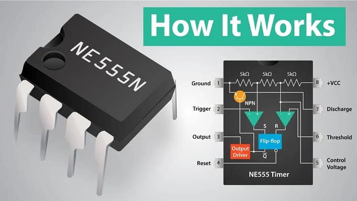
The basic principle of the 555 timer IC is based on the use of comparators, a flip-flop, a discharge transistor, and an external RC (resistor-capacitor) network to generate precise time delays or oscillations.
Internals & Principle
Here’s how it works in simple terms:
Core Components Inside 555:
Two comparators
One flip-flop (SR latch)
One discharge transistor
Voltage divider (three 5kΩ resistors)
⚙️ Basic Operating Modes:
1. Monostable Mode (One-shot pulse)
Function: Produces a single output pulse when triggered.
Principle:
You trigger the 555 (usually a falling edge).
A capacitor starts charging through a resistor.
Once voltage across the capacitor reaches 2/3 of the supply, output turns off.
Pulse width depends on R × C.
2. Astable Mode (Oscillator)
Function: Produces a continuous square wave (oscillates between HIGH and LOW).
Principle:
The capacitor charges/discharges between 1/3 and 2/3 of the supply voltage.
Internal comparators toggle the output based on capacitor voltage.
Frequency and duty cycle depend on two resistors and one capacitor.
3. Bistable Mode (Flip-Flop)
Function: Acts like an SR flip-flop—stays HIGH or LOW until manually triggered.
Principle:
Set and reset pins directly control the output state.
Thresholds Used Internally
1/3 VCC – triggers output HIGH.
2/3 VCC – resets output LOW.
These reference levels are created by the internal voltage divider (three 5k resistors = “555”).
What is the 555 IC?
The 555 IC (Integrated Circuit) is a versatile and widely used timing chip that can generate precise time delays, oscillations, and logic pulses. It was invented by Hans R. Camenzind in 1972 for Signetics (now part of ON Semiconductor).
Basic Facts:
Feature Description
Full Name NE555 Timer IC
Type Bipolar timer IC
Package DIP-8 (Dual Inline Package, 8 pins)
Power Supply 4.5V – 15V DC
Output Digital (0 or 1, i.e., LOW or HIGH)
Modes Monostable, Astable, Bistable
⚙️ Main Operating Modes:
Monostable Mode – One-shot pulse generator
Astable Mode – Square wave oscillator (multivibrator)
Bistable Mode – Flip-flop (set/reset latch)
| Pin No. | Name | Function |
|---|---|---|
| 1 | GND | Ground (0V) |
| 2 | Trigger | Starts timing when voltage drops below 1/3 Vcc |
| 3 | Output | Output signal (HIGH/LOW) |
| 4 | Reset | Resets the timer when pulled LOW |
| 5 | Control Volt. | Optional control of threshold (default = 2/3 Vcc) |
| 6 | Threshold | Ends timing when voltage reaches 2/3 Vcc |
| 7 | Discharge | Discharges timing capacitor |
| 8 | Vcc | Power supply (4.5V–15V DC) |
Fun Fact:
The name “555” comes from the three 5kΩ resistors in its internal voltage divider network.