

7-Segment Tester | Build This Simple DIY Tool
The 7-Segment Tester is a simple and effective DIY electronics project for quickly testing 7-segment displays. With a 7-Segment Tester, you can easily check each LED segment individually without connecting a microcontroller. This 7-Segment Tester uses a 9V power supply, a push button, and a resistor for safe testing. A 7-Segment Tester is especially useful for beginners, students, and repair technicians. By using a 7-Segment Tester, you can identify faulty displays and confirm whether a display is common cathode or common anode.
Building a 7-Segment Tester from scratch requires very few components, making it an affordable tool. A 7-Segment Tester allows fast troubleshooting during prototyping and repair work. With this 7-Segment Tester, hobbyists gain hands-on knowledge of LED displays. The 7-Segment Tester is a must-have tool in any electronics lab.
Introduction
If you have ever worked with LED 7-segment displays, you know how tricky it can be to check whether a display is working properly. A single faulty segment can lead to incomplete numbers, making your entire project look broken. Manually testing every pin with a power source is time-consuming.
That’s where the 7-Segment Tester comes in handy. This small DIY project allows you to test both common cathode and common anode 7-segment displays quickly. With just a few components, you can confirm whether each segment is lighting up correctly before using the display in your main circuit.
In this article, I’ll walk you through building a 7-Segment Tester from scratch, including the circuit diagram, BOM (Bill of Materials), explanation, and step-by-step construction guide.
By the end, you’ll have a reliable tool for your electronics lab!
Materials for the Project
| Component | Quantity | Description | Buy Link |
|---|---|---|---|
| 7-Segment Display | 1 | Common Cathode / Common Anode | Buy Link |
| Push Button (Tactile) | 1 | Momentary switch | Buy Link |
| Resistor 220Ω | 1 | Current limiting | Buy Link |
| Resistor 10KΩ | 1 | Pull-down resistor (optional) | Buy Link |
| DC Power Supply | 1 | 9V battery with connector | Buy Link |
| IC Socket (16-pin) | 1 | For easy testing of 7-segment displays | Buy Link |
| Jumper Wires | As needed | For connections | Buy Link |
| Perfboard | 1 | For permanent soldering | Buy Link |
Useful Tools
| Tool | Quantity | Purpose / Notes | Click & Buy |
|---|---|---|---|
| Soldering Iron Kit | 1 | For making permanent connections | Click & Buy |
| Solder Wire (60/40, 0.8mm) | 1 | Electrical soldering | Click & Buy |
| Wire Stripper & Cutter | 1 | Stripping jumper wires | Click & Buy |
| Mini Screwdriver Set | 1 | For module and relay terminal screws | Click & Buy |
| Multimeter | 1 | Testing voltages and continuity | Click & Buy |
| Hot Glue Gun (optional) | 1 | Securing components in place | Click & Buy |
| Small Pliers | 1 | Holding and bending wires | Click & Buy |
| Heat Shrink Tubing Set | 1 | Insulating exposed wires | Click & Buy |
Download Circuit Diagram

Circuit Diagram Explanation
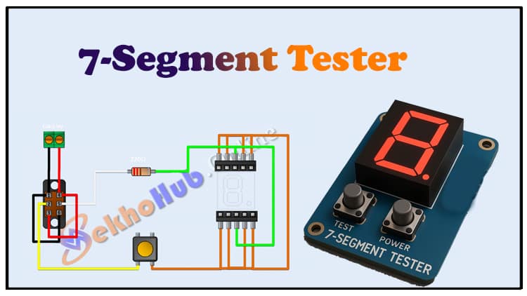
The 7-Segment Tester Circuit works on a very simple principle.
The 9V battery powers the circuit.
A 220Ω resistor is used to limit current before it reaches the LED segments, preventing damage.
The push button allows you to apply voltage to one segment at a time.
Each pin of the 7-segment display is wired to the socket. By pressing the button, current flows through the resistor into the selected segment, lighting it up.
This allows you to test every segment individually. If a segment doesn’t light up, the display is faulty.
For common cathode displays, the cathode pins are tied to ground, and you apply +V through the resistor to test segments.
For common anode displays, the anode pins are tied to +V, and you apply GND through the resistor to test segments.
Step-by-Step Building Guide
Follow these steps to build your own 7-Segment Tester:
Step 1: Power Supply
Connect a 9V battery (or adapter) to the circuit.
Use a terminal block or battery clip for convenience.
Step 2: Resistor Connection
Place a 220Ω resistor in series with the push button.
This resistor ensures that LED segments don’t burn out.
Step 3: Push Button Setup
Connect the push button between the resistor and the 7-segment pin.
Each press will light up a segment.
Step 4: 7-Segment Socket
Solder a 16-pin IC socket onto the perfboard.
Insert your 7-segment display into this socket for easy removal and testing.
Step 5: Wiring Segments
Connect each pin of the socket to the push button circuit.
Ensure proper orientation (dot on the display indicates pin 1).
Step 6: Testing
Insert a display into the socket.
Press the push button while touching each segment pin with a jumper wire.
If all segments light up correctly, the display is good.
Applications of 7-Segment Tester
The 7-Segment Tester is a small project but extremely useful. Some applications include:
✔️ Testing 7-segment displays before using them in circuits.
✔️ Identifying faulty segments in old or salvaged displays.
✔️ Distinguishing between common cathode and common anode displays.
✔️ Helping beginners learn how 7-segment displays work.
✔️ Useful tool for repair technicians and students in electronics labs.
Frequently Asked Questions (FAQs)
1. Can this tester work for both common cathode and common anode displays?
Yes! You just need to change the wiring of the common pin. For cathode, tie it to GND; for anode, tie it to Vcc.
2. Why is a resistor necessary?
The resistor (220Ω) limits current. Without it, the LED segments may burn out.
3. Can I use a lower voltage power supply?
Yes, 5V is also sufficient for most displays. Just adjust the resistor value (e.g., 100Ω–220Ω).
4. What if some segments don’t light up?
That means the display is faulty, or the wiring is incorrect. Try swapping to another display.
5. Can I make this tester on a breadboard?
Absolutely. Breadboards are great for quick prototyping before soldering.
Conclusion
The 7-Segment Tester Circuit is a simple yet powerful DIY tool for every electronics enthusiast. Instead of struggling with faulty displays during your projects, you can quickly test them beforehand using this tester.
With only a 9V battery, resistor, push button, and socket, you can build a reliable tester in less than an hour. Whether you’re a beginner learning electronics or a professional repairing circuits, this tool will save you time and effort.