
Understanding 74HC164: Practical Guide to 8-Bit Serial-In Parallel-Out Shift Register
The 74HC164 is an 8-bit serial-in, parallel-out shift register that allows you to expand microcontroller outputs using minimal pins. This guide covers the 74HC164 pinout, working principle, applications, and interfacing methods in detail. With a clear explanation of its internal logic, timing diagrams, and a real-world circuit example, this article is perfect for electronics engineers and hobbyists. You’ll also find a step-by-step tutorial on connecting the 74HC164 to an Arduino to drive multiple LEDs.
A full bill of materials (BOM), schematic explanation, and frequently asked questions are included for quick reference. By the end of this guide, you’ll have a complete understanding of how to use the 74HC164 effectively in your own projects. Whether you’re designing embedded systems or experimenting with digital electronics, the 74HC164 can help simplify wiring and optimize I/O usage in microcontroller-based applications.
1. Introduction
When you’re building digital projects, sometimes the number of microcontroller pins just isn’t enough. This is where 74HC164, an 8-bit serial-in parallel-out shift register, becomes incredibly handy. It takes data in serially (one bit at a time) and outputs it in parallel, effectively multiplying your available output pins.
It’s especially useful when driving LEDs, displays, or any set of digital outputs without overloading the microcontroller’s limited I/O capacity.
2. Features
8-bit serial-in parallel-out shift register
High-speed CMOS technology
Direct, clear input for resetting outputs
Wide supply voltage range (2V to 6V)
Outputs capable of driving TTL and CMOS loads
Low power consumption Understanding
Simple interfacing with microcontrollers
3. 74HC164 Pinout and Functions
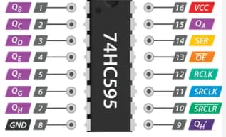
| Pin No. | Name | Description |
|---|---|---|
| 1 | A | Serial data input A |
| 2 | B | Serial data input B |
| 3 | QA | Output Q0 |
| 4 | QB | Output Q1 |
| 5 | QC | Output Q2 |
| 6 | QD | Output Q3 |
| 7 | GND | Ground |
| 8 | QE | Output Q4 |
| 9 | QF | Output Q5 |
| 10 | QG | Output Q6 |
| 11 | QH | Output Q7 |
| 12 | MR | Master Reset (active low) |
| 13 | CP | Clock input |
| 14 | VCC | Supply voltage |
| 15 | NC | Not connected |
| 16 | NC | Not connected |
4. How 74HC164 Works
The 74HC164 takes two serial data inputs (A and B) and combines them via an internal OR gate. Data is shifted into the register on each rising edge of the clock signal (CP). As bits shift in, the outputs (QA–QH) change, providing parallel outputs for each bit.
Master Reset (MR) clears all outputs to LOW when activated (logic 0).
This mechanism allows microcontrollers to send a stream of bits serially and then instantly have all outputs updated in parallel.
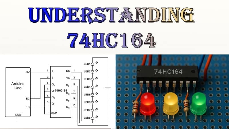
5. Circuit Diagram Explanation
In the example circuit:
Microcontroller Pins: Two pins are used—one for clock (CP) and one for data (A/B tied together).
Outputs: Each of the eight outputs drives an LED through a current-limiting resistor.
Power Supply: The 74HC164 is powered from the same supply as the microcontroller (5V for Arduino or 3.3V for some boards).
When data is sent bit-by-bit, each clock pulse shifts it along the register, lighting the LEDs in sequence.
Download Circuit Diagram

Materials for the Project
| S.No | Component | Quantity | Description |
|---|---|---|---|
| 1 | 74HC164 IC | 1 | 8-bit serial-in parallel-out shift register |
| 2 | Arduino Uno | 1 | Microcontroller board for control |
| 3 | LEDs | 8 | Output indicators |
| 4 | Resistors | 8 | 220Ω current limiting |
| 5 | Breadboard | 1 | Prototyping |
| 6 | Jumper wires | As needed | Connections |
| 7 | USB Cable | 1 | Power and programming |
7. Step-by-Step Guide
Step 1: Connect VCC (pin 14) to 5V and GND (pin 7) to ground.
Step 2: Connect Arduino pin D2 to 74HC164’s CP (pin 13).
Step 3: Connect Arduino pin D3 to A and B inputs (pins 1 and 2).
Step 4: Tie MR (pin 12) HIGH to enable outputs.
Step 5: Connect outputs QA–QH (pins 3–6, 8–11) to LEDs via resistors.
Step 6: Upload Arduino code that sends serial bits to control outputs.
8. Arduino Example Code
9. Applications
Driving multiple LEDs
Expanding microcontroller outputs
Controlling 7-segment displays
Building binary counters
Interfacing with sensors requiring parallel readout
10. FAQs
Q1: Can I cascade multiple 74HC164 ICs?
A: Yes, connect QH of one IC to the data input of the next.
Q2: What’s the maximum clock frequency?
A: Typically around 25 MHz at 5V supply.
Q3: Is it compatible with 3.3V logic?
A: Yes, but check the datasheet for exact voltage levels.