

Complete 74HC595 Projects | Easily Expand Arduino Inputs and Outputs
Master the 74HC595 shift register with this complete, beginner-friendly tutorial. Learn how to expand Arduino outputs, wire the circuit, and run example projects. Includes diagrams, step-by-step instructions, and expert tips for real-world applications. Ideal for LED displays, relay control, and other projects where more I/O pins are needed.
Introduction
If you’ve ever built a project with Arduino and run out of digital pins, you’ve faced the exact challenge that the 74HC595 solves. As a shift register IC, it lets you send data serially from your microcontroller and get parallel outputs on 8 separate pins. Over the last decade, I’ve used the 74HC595 in everything from LED chasers to industrial control panels—and it has never disappointed. In this guide, we’ll go through how it works, how to connect it, and a few projects you can build today.

74HC595 Pinout and Functions.
| Pin No. | Pin Name | Function |
|---|---|---|
| 1 | Q1 | Output pin 1 (bit 1 of storage register). Drives LEDs or loads. |
| 2 | Q2 | Output pin 2 (bit 2 of storage register). |
| 3 | Q3 | Output pin 3 (bit 3 of the storage register). |
| 4 | Q4 | Output pin 4 (bit 4 of storage register). |
| 5 | Q5 | Output pin 5 (bit 5 of the storage register). |
| 6 | Q6 | Output pin 6 (bit 6 of storage register). |
| 7 | Q7 | Output pin 7 (bit 7 of the storage register). |
| 8 | GND | Ground (0V reference). |
| 9 | Q7’ | Serial data output (used for daisy-chaining to the next 74HC595). |
| 10 | MR | Master Reset (Active LOW). Clears register when LOW. Usually tied to VCC for normal operation. |
| 11 | SH_CP | Shift Register Clock. On the rising edge, data in DS is shifted into the register. |
| 12 | ST_CP | Storage Register Clock (Latch). On the rising edge, transfers shift register contents to output pins Q0–Q7. |
| 13 | OE | Output Enable (Active LOW). When HIGH, outputs go to a high-impedance state. |
| 14 | DS | Serial Data Input. Data from Arduino enters here. |
| 15 | Q0 | Output pin 0 (bit 0 of storage register). |
| 16 | VCC | Positive supply voltage (+5V typical). |
What is the 74HC595 IC?
Type: 8-bit serial-in, parallel-out shift register with latch
Purpose: Expands microcontroller outputs without needing more pins
Package: 16-pin DIP or SMD
Voltage: Operates from 2V to 6V
Speed: Works reliably up to 20 MHz
How it works:
Your microcontroller sends bits (0 or 1) one at a time to the chip.
The chip stores these bits in its register.
When the latch pin is toggled, the bits appear on the output pins simultaneously.
Advantages of Using 74HC595?
Expands outputs using only 3 MCU pins
Daisy-chainable for more outputs (8 per chip)
Reduces wiring clutter in large projects
Cost-effective (often under $0.30 per IC)
Compatible with Arduino, Raspberry Pi, ESP32, and more
Materials for the Project
| Component | Quantity | Description |
|---|---|---|
| 74HC595 IC | 1 | 8-bit serial-in, parallel-out shift register |
| Arduino Uno | 1 | Main controller |
| LEDs | 8 | 5 mm LEDs |
| Resistors 220Ω | 8 | Current-limiting for LEDs |
| Breadboard | 1 | Prototyping board |
| Jumper wires | ~15 | Male-to-male |
| USB cable | 1 | For programming Arduino |
| Power supply | 1 | 5V source |
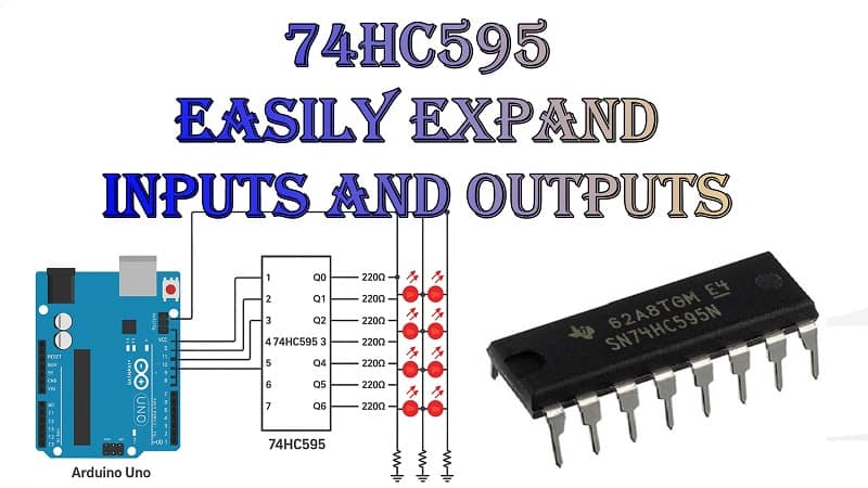
Circuit Diagram Explanation
Think of the 74HC595 as an “output expander.” Instead of dedicating 8 separate pins from your Arduino, you use only:
SER (DS) – Serial data in
SRCLK (SH_CP) – Shift register clock
RCLK (ST_CP) – Latch clock
Other pins:
OE – Output enable (active low) → connect to GND
MR – Master reset (active low) → connect to VCC for normal use
Q0–Q7 – Parallel outputs to LEDs or other loads
When data is shifted in via SER and SRCLK, it’s stored but not shown on the outputs until RCLK is toggled HIGH.
Download Circuit Diagram

Step-by-Step Wiring Guide
Connect VCC and GND from Arduino to the 74HC595.
Connect SER to Arduino pin 11.
Connect SRCLK to Arduino pin 12.
Connect RCLK to Arduino pin 8.
Tie OE to GND and MR to VCC.
Connect Q0–Q7 through 220Ω resistors to LEDs.
Upload the example sketch to Arduino.
Example Arduino Code
7 Project Ideas
7-segment display driver
LED matrix controller
Relay bank for automation
Traffic light simulator
Sensor data bar graph
Custom scoreboard display
FAQs
Q1: Can I use multiple 74HC595 chips?
A: Yes, daisy-chaining lets you add more outputs.
Q2: Can it drive high-current loads?
A: Not directly—use transistors or MOSFETs for heavy loads.
Q3: Is it compatible with 3.3V logic?
A: Yes, it works from 2V to 6V.