

HOW TO MAKE ARDUINO PLC | Arduino PLC 2.0 – Complete DIY Guide
[Sekhohub.online]
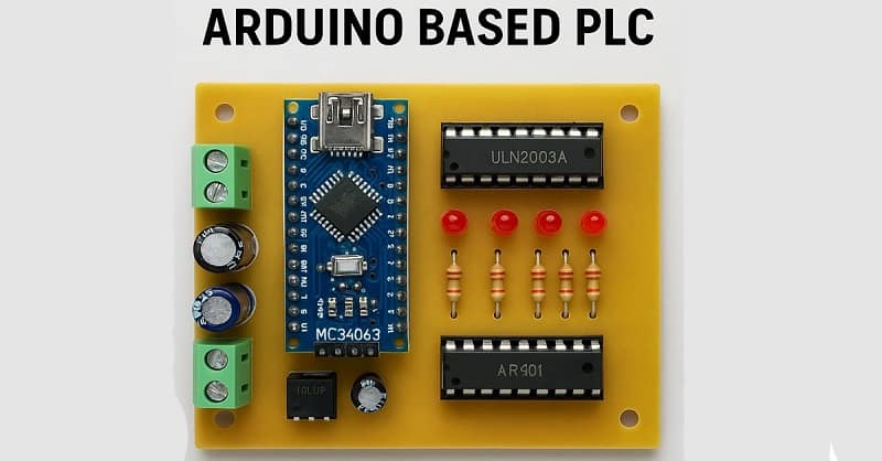
Welcome to SekhoHub, your one-stop destination for electronics and automation projects. In this blog, we’ll show you how to make an Arduino-based PLC (Programmable Logic Controller) using low-cost components like Arduino Nano, ULN2003A, PC817 optocoupler, and MC34063 buck converter.
This is Arduino PLC 2.0, an improved and professional version designed for real-world automation needs. It’s modular, isolated, and expandable—ideal for controlling relays, sensors, and even small machines.
Materials for the Project
- 1 X Arduino Nano
- 1 X ULN2003A IC
- 7 X PC817 Optocoupler
- 1 X MC34063 IC
- 14 X LEDS
- 1 X 1N5809 Diodes
- 1 X 330 mH Inductor
- 1 X 1n Capacitor
- 1 X 470u Capacitor
- 1 X 1R Resistor
- 14 X 1k Resistors
- 1 X 3.3k Resistor
- 10 X 10k Resistors
- 2x 12V Relays
- 14 X 2 Pin Terminal Block
- JUMPER WIRES
⚙️What is an Arduino PLC?
A PLC (Programmable Logic Controller) is an industrial digital computer used to control manufacturing processes, home automation, and smart systems. In our case, we are using an Arduino Nano as the core controller.
With proper input/output circuits and power isolation, you can create a fully functional, programmable, low-cost PLC.
Features of Arduino PLC 2.0
✅ Digital Inputs with Optocoupler Isolation (PC817)
✅ Output Control using ULN2003A Driver IC
✅ Onboard DC-DC Buck Converter (MC34063) to step down 12V to 5V
✅ USB programmable using Arduino IDE
✅ Expandable I/O pins
✅ Ideal for sensors, relays, indicators, alarms
Download Circuit Diagram
Circuit Diagram Project File
Download Gerber File
Gerber
Main Sections:
Input Section: PC817 optocoupler with 1K resistor and 10K pull-down to Arduino input.
Output Section: ULN2003A drives relays/LEDs with flyback diodes.
Power Supply: MC34063 converts 12V to 5V for Arduino Nano.
Wiring Overview
Inputs:
A 12V signal enters PC817 via a 1K resistor.
Output of PC817 connected to Arduino input pin and ground with 10K resistor.
Outputs:
Arduino output pins connected to ULN2003A inputs.
ULN2003A outputs connected to relays or indicators.
Power:
12V DC input into MC34063.
The MC34063 output provides regulated 5V to the Arduino.
Video Tutorial
⚡ Use Cases
Smart Home Control (lights, fans, alarms)
Automatic Water Pumps
Agricultural Systems (Irrigation, Soil Monitoring)
Industrial Machine Automation
Educational Labs and Training Boards
⚠️ Safety Tips
Always use optocouplers to isolate external signals.
Use flyback diodes on all relay coils to avoid voltage spikes.
Ensure proper 5V regulated power for Arduino.
Use insulated enclosures for final deployment.