
How to Make Delay Timer Switch Using BC547 Transistor
[Sekhohub.online]
Introduction
Want to control a device with a delay? This simple delay timer switch circuit using a BC547 transistor is perfect for beginners and hobbyists. It turns ON or OFF a device after a short delay and can be used in automation projects, light control systems, or simple security alarms.
Materials for the Project
1- 2X BC547 transistor
2- 1X 1N4007 diode
3- 1X 100uf 50V capacitors (electrolytic)
4- 1X 12V relay
5- 1X 47K resistors (1/4 watt)
6- 2X 10K resistors (1/4 watt)
7- 2X 1K resistors (1/4 watt)
8- 1X 3-pin terminal block
9- 1X 2-pin terminal block
10- 1X GREEN LED
11- 1X RED LED
12- vero board
13- jumper wires
Download Circuit Diagram

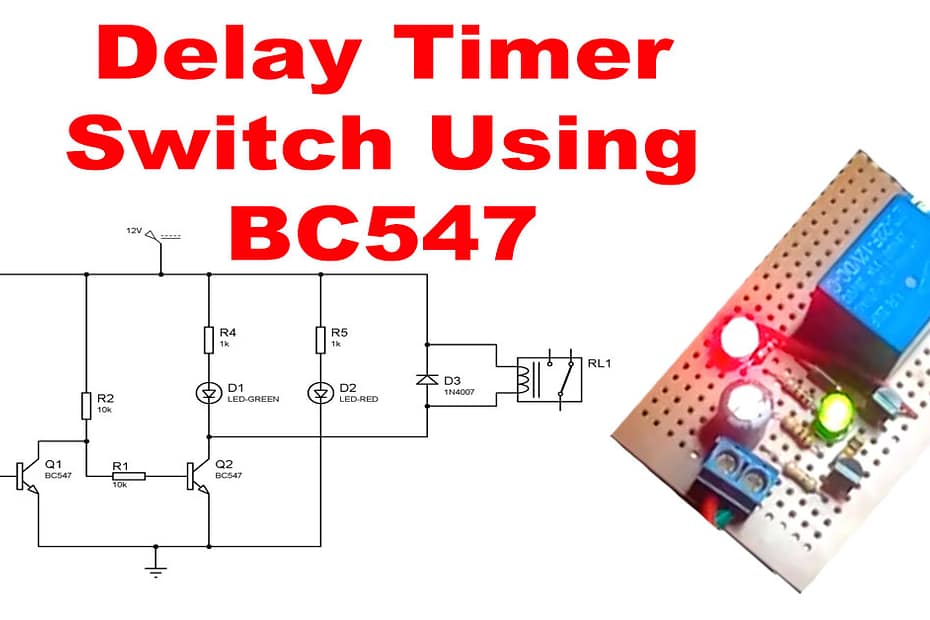
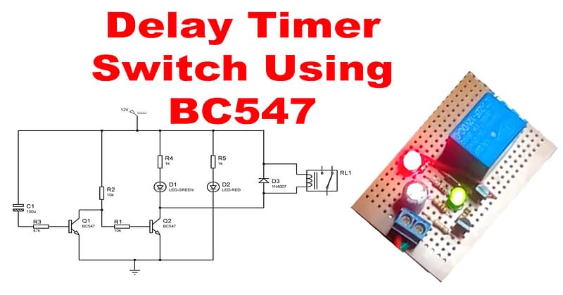
Circuit Diagram
⚙️ Circuit Explanation
The delay mechanism is created using the charging time of the capacitor (C) through the resistor (R). This forms an RC time constant.
Here’s how it works:
When the circuit is powered ON, the capacitor starts charging slowly through the 10kΩ resistor.
Once the voltage across the capacitor is enough to bias the BC547 transistor, it turns ON.
The transistor activates the relay, powering the connected device (light, fan, etc.)
The delay time depends on the values of the capacitor and resistor:
Higher capacitor = longer delay
Higher resistor = longer delay
Delay Time Formula (Approximate)
T≈R×CT \approx R \times C
Where:
T = Delay time in seconds
R = Resistance in ohms
C = Capacitance in farads
Example:
R = 10kΩ = 10,000 ohms
C = 470 µF = 0.00047 F
T ≈ 10,000 × 0.00047 = 4.7 seconds
Applications
Fan or light auto turn-off
Power-on delay for appliances
DIY battery charging timer
Security and automation systems