

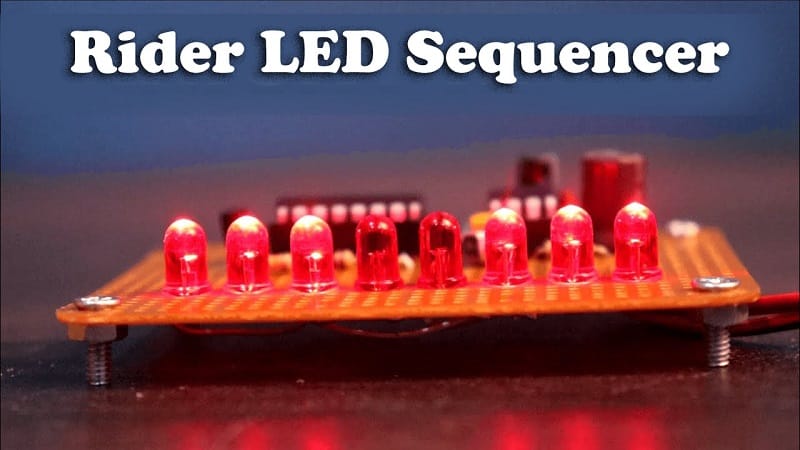
Rider LED Sequencer Light using CD4017 IC and 555 Timer IC
[Sekhohub.online]
✅ Introduction
The Rider LED Sequencer Light is a popular decorative and educational electronics project. It’s often seen in motorcycles, cars, or DIY LED displays where LEDs light up in a chasing or “rider” pattern. In this tutorial, we’ll build a simple and effective LED chaser circuit using a CD4017 Decade Counter IC and a 555 Timer IC.
Materials for the Project
- 1x 4017 IC
- 1x 555 IC
- 6x LEDs
- 1x nF Capacitor
- 1x 10uF Capacitor
- 1x 10k Variable Resistor
- 1x 100 Ohm Resistor
- 7x 470 Ohm Resistors
- 2x 1k Resistors
- 1x 10k Resistor
- Vero Board
- Jumper Wires
Circuit Diagram Overview
The 555 Timer IC is configured in astable mode to act as a pulse generator (clock). Each pulse is sent to the CD4017 IC, which then turns on LEDs one by one, creating a chaser or rider light effect.
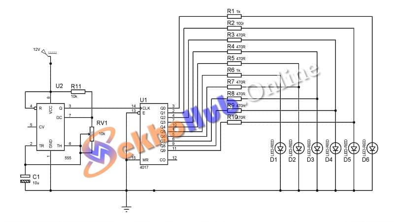
Download Circuit Diagram
Circuit Diagram
How the Circuit Works
555 Timer as Clock Generator
Generates continuous square pulses (ON/OFF signals).
Frequency is controlled by the resistor and capacitor values.
CD4017 as Decade Counter
Takes each pulse and activates its 10 outputs (Q0–Q9) sequentially.
Each output drives an individual LED.
LED Sequencing
The 10 LEDs light up in a flowing pattern.
Resets after Q9 and repeats the sequence.
Applications of LED Rider Light
Decorative lights for vehicles
Signal indicators
Electronics learning projects
Festive lighting systems
Embedded systems prototyping
Power Supply Suggestions
5V DC (USB power)
9V Battery (with connector)
12V Adapter (if LEDs and resistors are rated for higher voltage)
Conclusion
Creating a Rider LED Sequencer using CD4017 and 555 Timer IC is a fun and beginner-friendly electronics project. It helps you understand basic digital logic, ICs, and timing circuits. Whether you’re a student or a hobbyist, this project is a must-try for your toolkit.
For more DIY electronics circuits and tutorials, keep visiting SekhoHub.online—Pakistan’s growing platform for electronics learners and makers.