

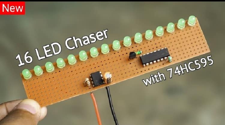
Falling Rain LED Light | DIY LED Chaser Light Circuit Using 74HC164 & 555 Timer
Looking for a creative LED project that gives a beautiful “falling rain” effect? In this blog, we’ll guide you step-by-step to make a Falling Rain LED Light Circuit using the 74HC164 Shift Register and the classic 555 Timer IC.
What is the 74HC164?
The 74HC164 is an 8-bit serial-in, parallel-out shift register. It takes serial data input and provides parallel output, making it perfect for LED sequencing.
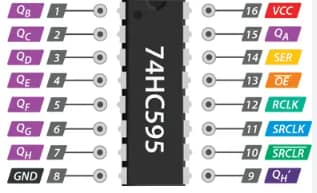
74HC164 Pinout:
| Pin | Name | Description |
|---|---|---|
| 1 | A | Serial Data Input (A) |
| 2 | B | Serial Data Input (B) |
| 3-6, 10-13 | Q0-Q7 | Parallel Outputs for LEDs |
| 7 | GND | Ground |
| 8 | CLK | Clock Input from 555 Timer |
| 9 | CLR | Clear (active LOW, connect to VCC) |
| 14 | VCC | Power Supply |
Materials for the Project
- 1X 74HC164 IC
- 1X 555 TIMER IC
- 1X BC547 TRANSISTOR
- 8X LEDS
- 1X 4.7uF CAPACITOR
- 1X 10K TRIMPOT
- 8X 100 OHM RESISTORS
- 3X 10K RESISTORS
- 1X BREADBOARD POWER SUPPLY
- 1X BREADBOARD
- 1X 9V POWER SUPPLY
- JUMPER WIRES
Download Circuit Diagram
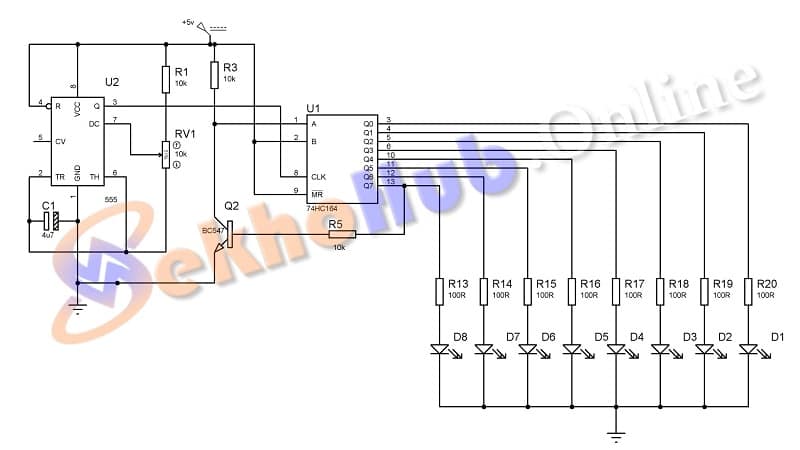
Circuit Explanation
The project is divided into two main sections:
1. 555 Timer as Clock Generator
- The 555 timer is set in astable mode.
- It continuously generates square wave pulses.
- These pulses are fed into the clock (CLK) pin of the 74HC164.
2. 74HC164 Shift Register for LED Chasing
- The IC receives serial HIGH (logic 1) on both data inputs A & B.
- With every clock pulse, the HIGH signal shifts from Q0 to Q7.
- Each output pin (Q0–Q7) lights up its respective LED in sequence.
- This creates a chaser or falling rain visual effect.
Circuit Connections
555 Timer (Astable Mode):
- Pin 1 (GND) → Ground
- Pin 2 (Trigger) → Connect to Pin 6
- Pin 3 (Output) → Connect to CLK pin of 74HC164 (Pin 8)
- Pin 4 (Reset) → VCC
- Pin 5 (Control) → 100 nF capacitor to GND
- Pin 6 (Threshold) → Connect to Pin 2
- Pin 7 (Discharge) → 10k resistor to VCC
- Pin 8 (VCC) → +5V
74HC164:
- Pin 1 (A) → VCC (logic HIGH)
- Pin 2 (B) → VCC (logic HIGH)
- Pin 3–6, 10–13 (Q0–Q7) → Each connected to LED (with Ω resistor) → GND
- Pin 7 (GND) → Ground
- Pin 8 (CLK) → 555 Timer Output (Pin 3)
- Pin 9 (CLR) → VCC
- Pin 14 (VCC) → +5V
How It Works
- The 555 timer outputs clock pulses.
- 74HC164 receives HIGH on A & B inputs.
- Each clock pulse shifts the HIGH bit from one output (Q0) to the next (Q1, Q2… Q7).
- LEDs light up one by one like raindropsfalling.
- When all outputs are HIGH, the shifting restarts.
Applications
- Decorative LED lighting
- Project showcases
- Learning digital electronics and shift registers
- Visual indicators and sequence controllers
✨ Extra Tips
- Add a potentiometer (10k) to control the speed of the LED chase.
- Use multiple 74HC164s to extend the sequence beyond 8 LEDs.
- Combine with sound or sensor input for interactive projects.
Final Thoughts
This project is a great introduction to digital logic and LED effects. The 74HC164 is easy to use and adds dynamic visual feedback to any circuit. Try building it on a breadboard first, then transfer to PCB for permanent display.