
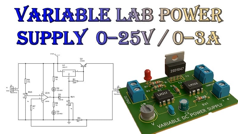

How to Make a Variable Lab Power Supply | Adjustable Voltage 0–25V and Current 0–3A
Whether you’re an electronics hobbyist, DIY maker, or student, one of the most valuable tools on your bench is a variable power supply. But commercial units can be expensive. So why not build one yourself? In this tutorial, you’ll learn how to make variable lab bench power supply using simple and affordable components like the LM317 voltage regulator, LM358 operational amplifier, and 2SD1047 power transistor.
We’ll cover everything from circuit design to testing—and by the end, you’ll have a working lab power supply that delivers 0–25V adjustable voltage and up to 3A of current, complete with current limiting functionality.
Contents Table
- Why Build Your Own Power Supply?
- Features of This Power Supply
- Understanding the Circuit
- Circuit Diagram Overview
- Testing & Calibration
- Thermal Management
- Safety Tips
- Troubleshooting Tips
- Final Thoughts
Why Build Your Own Power Supply?
Think of it like building your own Swiss army knife for electronics. Need 5V for a microcontroller? 12V for a motor? 3.3V for sensors? Instead of juggling batteries or buying multiple adapters, this one unit does it all—safely and efficiently. Plus, when you build it yourself, you learn the core concepts of voltage regulation, current control, and thermal management.
Materials for the Project
- 1X LM317 IC
- 1X LM358 IC
- 1X 2SD1047 TRANSISTOR
- 1 × 1N4148-DIODEN
- 2X LED
- 1X 1000uF CAPACITOR
- 1X 5K POTENTIOMETERS
- 1X 0.1 OHM RESISTOR
- 1X 220 OHM RESISTOR
- 1X 1K RESISTOR
- 1X 10K RESISTOR
- 1X 470K RESISTOR
- 2X 2 PIN TERMINAL BLOCKS
- 1X PERF BOARD
- JUMPER WIRES
Features of This Power Supply
Here’s what makes this power supply a perfect DIY lab companion:
Input Voltage: 24–30V DC or from a step-down transformer
Adjustable Output Voltage: 0 to 25V
Adjustable Current Limit: 0 to 3A
Voltage Regulation: LM317-based
Current Limiting: Controlled by LM358 op-amp
Pass Transistor: 2SD1047 for high current handling
Built-in protection: Against short circuits and overheating
Optional Add-ons: Volt/Amp display, cooling fan, USB output
Download Circuit Diagram

Gerber Files
Understanding the Circuit
1. Power Input and Filtering
Start with a 24V AC transformer, which is then converted to DC using a bridge rectifier and smoothed using a large capacitor (4700 µF or more).
2. Voltage Regulation with LM317
The LM317 is a classic adjustable regulator. You control the output voltage using a potentiometer connected to its adjustment pin. However, it can only output 1.5A by itself. That’s where the 2SD1047 transistor comes in—it acts like a muscle, boosting the current capacity up to 3A or more.
3. Current Limiting with LM358
Here’s the clever part. A low-value resistor (e.g., 0.47 Ω) is placed in series with the load. The voltage across this resistor is proportional to the current. The LM358 op-amp senses this voltage and compares it to a reference (set by a potentiometer). If the current exceeds the set limit, the op-amp reduces the gate/base drive of the regulator—effectively limiting the output current.
Circuit Diagram Overview
LM317 setup:
Vin: Connected to rectified, filtered 30V
Vout: Goes to output via the 2SD1047
Adj: Connected through a voltage-setting potentiometer
2SD1047 transistor:
Collector to LM317 output
Emitter to output terminal
Base controlled via LM317 through a resistor (about 100Ω)
Current sensing path:
0.47Ω 5W resistor in series with output
Voltage across this goes to LM358 input
LM358 output feeds back to LM317 adjust pin to reduce voltage under overcurrent
Testing & Calibration
✅ First Power-On
Use a multimeter to measure the output voltage.
Turn the voltage potentiometer to vary voltage from 0 up to 25V.
Adjust the current control by connecting a dummy load (e.g., a high-wattage resistor or car headlamp).
Current Limiting Test
Set the current to 1A using the current pot.
Connect a load that tries to draw more (like a 2A load).
If the current stays at 1A and voltage drops — the limiter works!
Thermal Management
Both the LM317 and 2SD1047 can get very hot under high loads. So:
Use large aluminum heatsinks
Add a 12V cooling fan if you’re running close to 3A
Make sure your enclosure is ventilated
Safety Tips
Always unplug the power supply when making modifications.
Never touch components when powered, especially capacitors they can hold charge.
Use a fuse on the AC side.
Double-check polarity before connecting loads.
Troubleshooting Tips
| Issue | Possible Cause |
|---|---|
| No output voltage | Check transformer, bridge, or LM317 wiring |
| Output stuck at 1.25V | LM317 adjust pin not connected properly |
| Overheating | Inadequate heatsink or airflow |
| Voltage drops with load | Current limit too low or bad transistor |
| Display not working | Wrong wiring or reverse polarity |
Real-World Use Cases
Testing microcontrollers or Arduino boards
Running small DC motors, fans, or relays
Charging batteries (with caution)
Breadboard power source
Bench testing DIY circuits safely
Final Thoughts
Building a variable power supply like this isn’t just a project it’s an investment in your electronics journey. You’ll understand voltage regulation, current control, power dissipation, and most importantly