


16-LED Running Light Circuit with 555 Timer and 74HC595 | Simple LED Chaser Project
16-LED running light circuit is an exciting project that combines the functionality of a 555 timer IC and a 74HC595 shift register. This circuit is a great example of how simple digital components can come together to produce eye-catching visual effects, such as a sequential LED chaser. In this article, we’ll dive deep into how this circuit works, the role of each component, and how you can build it yourself.
What is a running light circuit?
A running light (or LED chaser) is a circuit where LEDs turn on and off sequentially, giving the illusion of motion. This pattern is commonly used in:
- Car indicators
- LED decorations
- Visual displays
- Signal and status indicators
In this version, 16 LEDs light up one by one, powered by a clock pulse generated from a 555 timer and controlled by a 74HC595 shift register.
Materials for the Project
Here’s the complete list of components needed to assemble the circuit, all visible in the provided schematic:
| Component | Value/Model | Purpose |
| IC1 | NE555P | Timer IC—Generates clock pulses |
| IC2 | 74HC595N | Shift register – Drives the LEDs |
| Q1 | BC547 | NPN Transistor – Reset logic |
| R1, R3, R4 | 2.2 kΩ | Sets timing and controls current |
| R2 | 15 kΩ | Sets delay for 555 timer |
| R5, R6 | 68Ω | Current limiting resistors for LEDs |
| C1 | 10 µF/50 V | Timing capacitor for 555 |
| LED1–LED16 | 5mm Red LEDs | Visual output |
| Power Source | +5V DC | Supplies power to the circuit |
Download Circuit Diagram
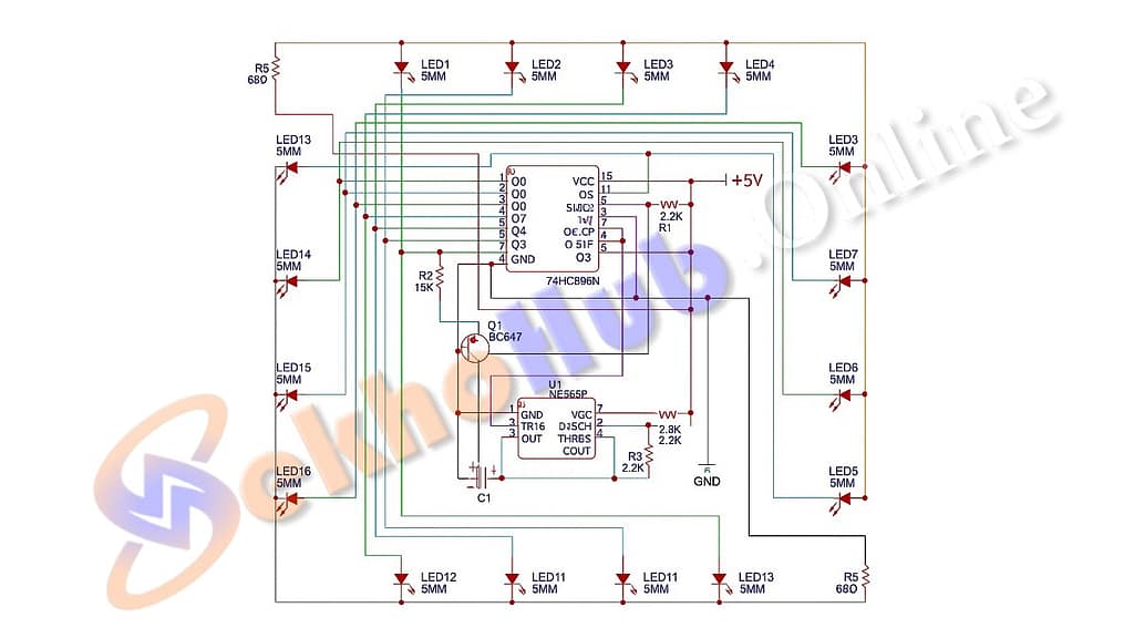
️ Circuit Diagram Overview
The NE555 timer’s output to the 74HC595 shift register is clearly depicted in this schematic, as is the connection of the LEDs to each register output pin.
⚙️ Working Principle
This circuit revolves around two main ICs:
1. 555 Timer as Clock Generator
The NE555P IC is configured in astable mode, generating a square wave (clock signal). This output (from pin 3) is connected to the clock (SH_CP) pin of the 74HC595.
- The resistors R2 (15 kΩ), R3 and R4 (2.2 kΩ), and the capacitor C1 (10 µF) determine the oscillation frequency.
- As this pulse repeats, it drives the 74HC595 to shift its bits and activate one LED at a time.
2. 74HC595 Shift Register
The 74HC595N is a serial-in, parallel-out register. It takes serial data from one pin and spreads it across 8 output pins.
- We only use one 74HC595N, but by shifting bits intelligently, we create a running pattern across 16 LEDs.
- Using a wrapping layout, output pins Q0 to Q7 are connected to 16 LEDs to create the appearance of two registers.
The trick lies in reusing the register’s output through proper resetting and data feeding to create the 16-step sequence.
Role of Each Component
NE555P – Timer IC
- Pin 1: GND
- Pin 2: Trigger, connected to threshold
- Pin 3: Output to 74HC595 Clock
- Pin 4: Reset, connected to VCC
- Pin 5: Control voltage (optional decoupling capacitor)
- Pin 6: Threshold
- Pin 7: Discharge
- Pin 8: VCC
Through the shift register, the 555 continuously generates pulses that drive the LEDs.
74HC595N – Shift Register
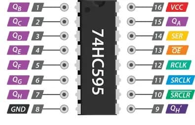
- DS (Serial Data Input): Receives data bit
- SH_CP (Shift Clock): Shifts data on rising edge
- ST_CP (Latch Clock): Transfers data to output
- MR (Master Reset): Resets register if pulled LOW
- OE (Output Enable): Usually tied to GND to keep outputs active
Only three pins are needed to control all LEDs: Data, Clock, and Latch, making this IC ideal for saving microcontroller I/O pins in advanced designs.
⚡ BC547 – Transistor
The shift register’s reset function is managed by the BC547 NPN transistor.
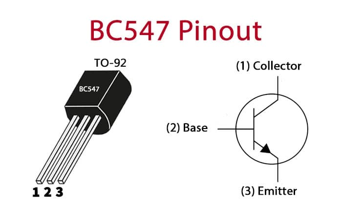
- Connected to the MR (Master Reset) pin
- Ensures the register resets after all LEDs are lit
- Helps in recycling the signal for continuous running
LEDs and Resistors
- Each LED is connected via a 680Ω resistor to prevent overcurrent.
- The anodes of LEDs receive the shift register’s outputs, and the cathodes are connected to ground.
- This limits current to about 7 mA per LED from a 5 V source, ensuring safe operation.
Step-by-Step Construction Guide
Follow these steps to assemble the circuit:
- Place the NE555 IC and 74HC595 on a breadboard.
- Wire the 555 in astable mode with:
- R2 (15kΩ), R3, R4 (2.2kΩ), and C1 (10µF)
- Connect the 555’s output (pin 3) to the SH_CP (clock) of the 74HC595.
- Pull up the ST_CP (latch) pin with a 2.2 k resistor (R1).
- Connect the BC547 transistor between the GND and MR (reset) pin.
- Add 680Ω resistors in series with each LED.
- Attach 16 LEDs from Q0 to Q7, 8 on the left and 8 on the right (refer to schematic).
- Using a regulated +5V DC supply, power the circuit.
- Watch the LEDs light up in a running pattern!
How the Running Light Works
Each time the 555 timer outputs a pulse:
- The 74HC595 shifts a HIGH bit (1) to the next output pin.
- Only one LED is ON at a time, creating a “running” or “chasing” effect.
- Once all 16 LEDs are lit in sequence, the transistor resets the shift register.
- The process repeats indefinitely, producing continuous motion.
Circuit Behavior and Timing Control
You can adjust the LED speed by tweaking the resistor and capacitor values in the 555 timer circuit:
| Component | Effect |
| Increase C1 (10 µF). | Slower blinking |
| Increase R2 (15 kΩ). | Longer ON time |
| Decrease resistors/capacitors. | Faster running effect |
Use a potentiometer in place of R2 for real-time speed adjustment.
✅ Applications
This running light circuit is ideal for:
- Educational experiments
- Car/bike indicator simulation
- LED decorations or toys
- Learning serial-to-parallel data control
- Understanding digital logic circuits
Troubleshooting Tips
| Issue | Because | Solution |
| LEDs not lighting | Wrong polarity or no power | Check LED direction and supply |
| Only one LED stays ON | Shift register not shifting | Verify 555 output pulses |
| Flickering | Noisy power or missing decoupling | Add 0.1 µF near ICs |
| Speed too fast/slow | Wrong R/C values | Adjust R2/C1 in timer section |
Expand This Project
Want more? Try these upgrades:
- Chain multiple 74HC595s for 24 or 32 LEDs.
- Use a microcontroller (Arduino) to control custom patterns.
- Create a bi-directional LED chaser.
- Add sound-activated running lights using a mic module.
Conclusion
This 16-LED running light circuit is a perfect entry-level project that mixes analog and digital electronics. With just a 555 timer, a 74HC595 shift register, and a few common components, you can build an eye-catching LED display and learn the core concepts of timing and serial data logic.
SEO Keywords:
- LED running light circuit
- NE555 timer project
- 74HC595 LED chaser
- electronics hobby project
- digital logic LED circuit
- LED shift register tutorial.