

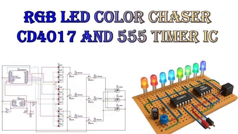
RGB LED Color Chaser Circuit Using CD4017 and 555 Timer IC
Introduction
LED chaser circuits are one of the most exciting and visually appealing projects for electronics enthusiasts. They combine creativity with fundamental electronics principles to create dynamic light patterns. In this tutorial, we will build an RGB LED Color Chaser Circuit using two classic ICs—the CD4017 Decade Counter and the NE555 Timer.
This project produces a colorful running light effect on 5 mm RGB LEDs by sequencing red, green, and blue colors in a pattern. The design uses simple, low-cost components and does not require a microcontroller, making it an excellent choice for beginners and hobbyists.
How It Works
The circuit operates in two main stages:
- Clock Pulse Generation – The NE555 Timer IC is configured in astable mode to generate continuous clock pulses.
- LED Sequencing—The CD4017 Decade Counter IC uses these pulses to activate its output pins sequentially, controlling transistors that drive the RGB LEDs in a colorful sequence.
Materials for the Project
Item No. Component Specification Quantity Reference 1 Decade Counter IC CD4017 1 U1 2 Timer IC NE555 1 U2 3 NPN Transistor BC547B 3 Q1, Q2, Q3 4 PNP Transistor BC557B 3 Q4, Q5, Q6 5 Diode 1N4007 12 D1–D12 6 Resistor 6.8 kΩ, 1/4 W 3 R1, R2, R3 7 Resistor 220 Ω, 1/4 W 1 R4 8 Resistor 150 Ω, 1/4 W 1 R5 9 Resistor 47 Ω, 1/4 W 1 R6 10 Resistor 1 kΩ, 1/4 W 2 R7, R8 11 Resistor 22 kΩ, 1/4 W 1 R9 12 Capacitor 100 µF / 25V Electrolytic 1 C1 13 RGB LED (Common Cathode) 5 mm 3 U3, U4, U5 14 Power Supply +5V DC Regulated 1 —
Download Circuit Diagram

Circuit Diagram Explanation
Three functional sections comprise the circuit diagram:
1. Pulse Generation with NE555 Timer
- The NE555 Timer IC is wired in astable mode.
- R8 (1 kΩ), R9 (22 kΩ), and C1 (100 µF) determine the output frequency.
- Through the NE555’s output, clock pulses are transmitted to the CD4017’s clock pin (pin 14).
- The rate at which the LEDs chase each other is determined by the frequency.
2. CD4017 Output Sequencing
- The CD4017 Decade Counter sequentially sets its output pins Q0 to Q9 HIGH in response to each clock pulse.
- Outputs are combined through 1N4007 diodes to control which transistors turn ON at a given moment.
- This design allows multiple outputs to overlap, creating mixed RGB colors.
3. Transistor Driver Stage
- BC547B (NPN) transistors receive logic signals from the CD4017 outputs via diodes.
- Each NPN transistor controls a BC557B (PNP) high-side driver transistor.
- The PNP transistors feed power to specific RGB LED pins (red, green, or blue).
- Current-limiting resistors (220 Ω, 150 Ω, 47 Ω) protect each color channel of the RGB LEDs.
Working Principle Step-by-Step
- Pulses are continuously delivered to the CD4017 IC by the NE555 timer.
- The CD4017 activates one of its outputs at a time.
- The activated output passes through diodes to the base of the NPN transistor.
- The PNP transistor in question is turned on by the NPN transistor.
- The PNP transistor allows current to flow through the selected color channel of all RGB LEDs.
- This sequence repeats, creating a smooth chasing effect with various color combinations.
Advantages of Using CD4017 and 555 Timer
- No microcontroller required—ideal for beginners.
- Low cost and easy to assemble.
- Customizable patterns by changing diode wiring.
- Speed control by adjusting resistor or capacitor values in the NE555 circuit.
Applications
- Decorative lighting systems
- Stage or event lighting effects
- Science fair demonstration projects
- Learning tool for digital logic and transistor switching
Tips for Customization
- Change the chasing speed: Adjust R9 or C1 in the 555 timer circuit.
- Add more LEDs: Connect additional RGB LEDs in parallel with each output, ensuring each has its own current-limiting resistor.
- Create new patterns: Rearrange the diode connections to mix different colors in sequence.
Troubleshooting Guide
- No LED lighting—Check power supply and transistor orientation.
- All LEDs on at once—Check for shorted diodes or wrong CD4017 connections.
- Uneven brightness—Adjust resistor values to balance current for each color.
Conclusion
An entertaining, vibrant, and instructive electronics project is the RGB LED Color Chaser Circuit, which uses a CD4017 and a 555 Timer IC. It’s perfect for hobbyists who want to learn about digital counters, timing circuits, and transistor switching while creating a visually stunning LED effect.
By understanding each component’s role, you can modify the design for different effects, making it a versatile addition to your electronics knowledge.
Primary Keywords.