

How To Make Powerful 3.6V Battery Charger at Home | With Cutoff
Charging small batteries like 3.6V Li-ion or NiMH packs requires more than just supplying voltage. To maintain battery life and prevent damage, a proper charging circuit with automatic cutoff is essential. In this guide, we will build a 3.6V battery charger with cutoff using an LM393 comparator, a MOSFET, and a few other basic components.
This design automatically stops charging when the battery reaches the set voltage level, ensuring safe operation. It’s perfect for rechargeable batteries used in cordless phones, toys, or portable devices.
How the Circuit Works
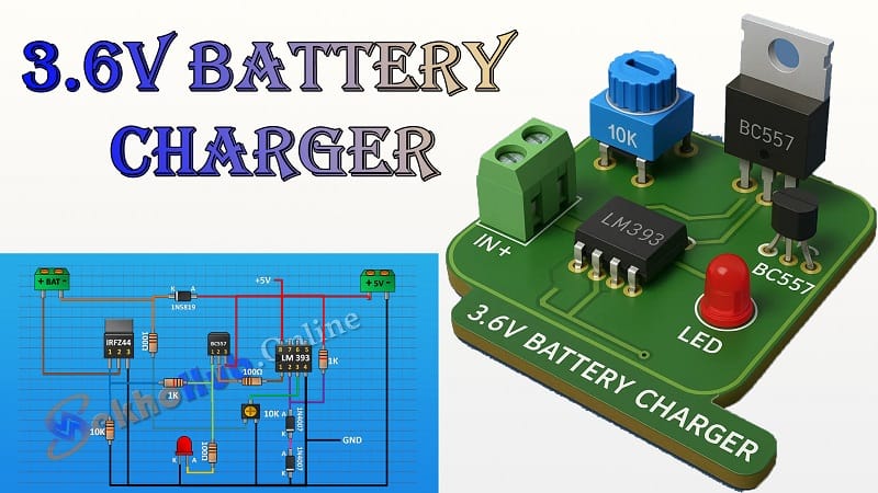
The charger uses the LM393 IC, a dual comparator, to monitor battery voltage. When the battery voltage reaches the preset cutoff point (around 4.2V for a single-cell Li-ion or 3.6V nominal), the comparator output changes state, turning off the MOSFET (IRFZ44). This disconnects the battery from the charging source automatically.
The BC557 transistor acts as part of the control circuit for the MOSFET, while diodes 1N4007 and 1N5819 handle polarity protection and reverse current blocking. The LED indicator shows charging status.
The 10K variable resistor allows you to adjust the cutoff voltage precisely. This makes the circuit adaptable for slightly different battery chemistries.
Materials for the Project (3.6V Battery Charger)
Main Components
- 1 × LM393 IC – Dual Comparator
- 1 × BC557 – PNP Transistor
- 1 × IRFZ44 – N-Channel MOSFET
Diodes
- 2 × 1N4007 – General Purpose Diodes
- 1 × 1N5819 – Schottky Diode
Indicators and Control
- 1 × LED – Charging status indicator
- 1 × 10K Variable Resistor – For voltage adjustment
Resistors
- 2 × 100Ω Resistors
- 2 × 1kΩ Resistors
- 1 × 10kΩ Resistor
Connectors and Wiring
- 2 × 2-Pin Terminal Blocks – For input and battery connection
- Jumper Wires – For circuit connections
Board
- 1 × Vero Board – For mounting components
Download Circuit Diagram

Circuit Diagram Overview
The circuit is built around the LM393. One comparator monitors the battery voltage via a voltage divider (made from fixed resistors and the 10K variable resistor). The comparator output drives the BC557, which in turn controls the IRFZ44 MOSFET.
- When battery voltage is below the set limit, the comparator keeps the MOSFET on, allowing current to flow from the supply to the battery
- Once the voltage reaches the cutoff threshold, the comparator output changes, switching off the MOSFET. This stops charging instantly.
- The LED is connected in such a way that it lights up during charging and turns off when charging stops.
Step-by-Step Assembly Guide (3.6V Battery Charger)
1. Prepare the Vero Board
Cut the Vero board to a suitable size. Plan the layout so the IC, MOSFET, and terminal blocks are positioned logically for wiring convenience.
2. Install the LM393
Mount the LM393 IC with its notch facing left or right (consistent with your diagram). Leave enough space for resistor and potentiometer connections.
3. Add the Resistors and Potentiometer
Place the resistors according to the schematic. Install the 10K variable resistor near the LM393 for easy voltage adjustment later.
4. Fit the Transistor and MOSFET
Mount the BC557 and IRFZ44. Attach a small heat sink to the MOSFET if you expect to charge at higher currents (over 1A).
5. Add the Diodes
- Use 1N4007 for input polarity protection.
- Use 1N5819 at the battery output to prevent reverse current flow when the charger is off.
6. Install the LED
Place the LED with correct polarity. Connect it through a suitable current-limiting resistor (typically 1kΩ).
7. Wire the Terminal Blocks
Connect one terminal block to the DC input (5–9V supply) and the other to the battery output.
8. Double-Check Connections
Verify all polarities, resistor values, and MOSFET orientation. Wrong connections can damage the components.
Adjusting the Cutoff Voltage
- Connect a fully charged battery (or a regulated power supply set to the target voltage) to the battery terminals.
- Adjust the 10K potentiometer slowly until the LED just turns off (MOSFET turns off).
- Disconnect and reconnect the battery to verify the cutoff action.
Testing the Charger
- Start with a partially discharged battery (e.g., around 3.5V for Li-ion).
- Connect the charger and observe the LED — it should light up, indicating charging.
- Monitor voltage with a multimeter. When it reaches the set cutoff (e.g., 4.2V), the LED should turn off and charging should stop automatically.
Advantages of This Design
- Automatic Cutoff: Prevents overcharging, which extends battery life.
- Adjustable Voltage: Works for different battery chemistries.
- Simple and Low-Cost: Uses commonly available components.
- Compact Size: Easily fits on a small Vero board.
Safety Tips
- Never leave batteries unattended while charging.
- Use the correct cutoff voltage for your battery type:
- Li-ion: ~4.2V
- NiMH/NiCd: Slightly above nominal voltage, depending on cells
- Ensure proper heat sinking for the MOSFET at higher charging currents.
- Always double-check polarity before connecting the battery.
Possible Improvements
- Add a second LED to indicate “fully charged” status.
- Integrate a current limiting resistor or constant current circuit for safer charging.
- Use a proper enclosure for durability and safety.
Related Articles (Internal Links)
You can also check:
- Transistor Basics and Working Principle
- How to Test Electronic Components with a Multimeter
- DC Power Supply Circuit Diagram
FAQ – 3.6V Battery Charger with Cutoff
Q1: Can this circuit charge Li-ion and NiMH batteries?
Yes. By adjusting the cutoff voltage with the potentiometer, it can work for both Li-ion and NiMH packs. Just ensure you set the correct cutoff point.
Q2: What is the maximum charging current?
It depends on the MOSFET, power supply, and wiring. With IRFZ44 and proper heat sinking, you can easily handle up to 3A, but for small batteries, 500mA–1A is recommended.
Q3: Can I use a 12V adapter as the input?
Yes, but ensure you include proper current limiting and that the MOSFET and heat sink can handle the power dissipation.
Q4: How accurate is the cutoff voltage?
The LM393 provides good accuracy, but fine-tuning with a multimeter is important for battery safety.
Q5: Is this charger safe for continuous connection?
Once the cutoff is triggered, the battery is disconnected from charging, so it’s safe to leave connected for short periods. However, it’s better to remove the battery when fully charged.