
 Smart DIY 4-in-1 AC Meter with Arduino Nano | Advanced Voltage, Current, Power, and Watt Step-by-Step
 Smart DIY 4-in-1 AC Meter with Arduino Nano | Advanced Voltage, Current, Power, and Watt Step-by-Step
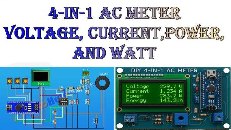
Build your own 4-in-1 AC meter using Arduino Nano to measure voltage, current, power, and watts in real time. This detailed DIY guide explains the circuit diagram, required components, and step-by-step assembly process for creating a precise AC monitoring system.
Learn how to interface an OLED display with Arduino Nano and use sensors like CT transformers and LM358 IC for accurate readings. Perfect for hobbyists, engineers, and DIY enthusiasts looking to create a reliable AC measurement tool for home or lab use. The design is easy to assemble on a perf board with basic soldering skills. Includes FAQs, wiring instructions, and calibration tips to ensure the accuracy of your project. By following this tutorial, you’ll have a fully functional AC meter ready for use in energy monitoring, testing, and educational purposes.
Introduction
When working with AC-powered devices, it’s essential to know exactly how much voltage, current, power, and wattage they consume. Instead of buying a commercial energy meter, you can build your own AC monitoring system for a fraction of the cost—and learn a lot along the way.
This DIY 4-in-1 AC Meter project uses an Arduino Nano as the brain, an OLED display for real-time data, and a current transformer (CT) paired with an LM358 IC for precise current measurement. With just a few components, you’ll have a versatile, portable, and accurate measurement tool for your workbench.
Features
Measures AC Voltage (50 Hz or 60 Hz systems)
Measures AC Current
Calculates Power (Watts)
Displays Real-Time Readings on an OLED Display
Compact, portable, and easy to assemble
Materials for the Project (4-in-1 AC Meter)
| No. | Component | Quantity | Specification / Notes |
|---|---|---|---|
| 1 | Arduino Nano | 1 | Microcontroller board |
| 2 | OLED Display | 1 | 0.96″ I2C, 128×64 pixels |
| 3 | Current Transformer (CT) | 1 | 100A/50mA (2000:1) ratio |
| 4 | LM358 IC | 1 | Dual Op-Amp |
| 5 | 47Ω Resistor | 1 | 1/4 W |
| 6 | 2.2K Resistor | 1 | 1/4 W |
| 7 | 4.7K Resistor | 1 | 1/4 W |
| 8 | 10K Resistor | 3 | 1/4 W |
| 9 | 470K Resistor | 6 | 1/4 W |
| 10 | 2-Pin Terminal Block | 2 | For AC input/output |
| 11 | Perf Board | 1 | General-purpose PCB |
| 12 | Jumper Wires | — | Male-to-male or soldered |
Download Circuit Diagram
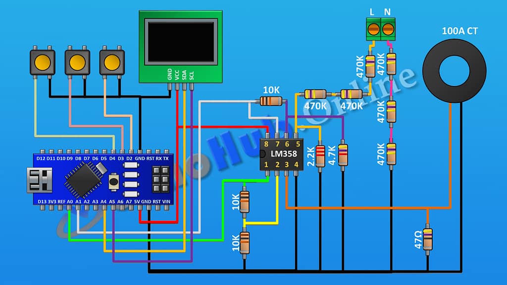
Circuit Diagram Explanation (4-in-1 AC Meter)
The project has two main sensing parts—voltage sensing and current sensing.
1. Voltage Sensing
Uses a resistor divider network (470K and 10K resistors) to bring high AC voltage down to a safe measurable level for the Arduino.
The signal is rectified and filtered before feeding into the Arduino’s analog pin.
2. Current Sensing
The CT transformer detects the magnetic field around the conductor, producing a small AC signal proportional to the current.
The LM358 op-amp amplifies and offsets this signal so it’s readable by the Arduino.
3. Display
The OLED screen shows all four parameters—voltage, current, power, and watt-hour—updated in real time.
⚠ Safety Note: Always be cautious when working with AC mains. Use proper insulation and safety equipment.
Step-by-Step Build Guide (4-in-1 AC Meter)
Step 1.
First connect Arduino.
Step 2.
then connect LM358 IC and connect its pin number one to A0 pin of
Arduino It’s pin number two to the A7 pin of Arduino. Its pin number eight is connected to the 5V pin of the Arduino, and its pin number four is connected to ground.
Step 3.
Now connect a 10k resistor and connect its one pin to pin number one of the IC and its other pin to pin number two of the IC.
Step 4.
Now connect another 10k resistor and connect one of its pins to pin number two of the IC and its other pin to ground.
Step 5.
Now connect the 47-ohm resistor and connect its one pin to pin number three of the IC and its other pin to ground.
Step 6.
Now connect the current transformer and connect its one pin to pin number three of the IC and its other pin to ground.
Now connect a 10k resistor and connect its one pin to pin number seven of the IC and its other pin to pin number six of the IC.
Step 7.
- Now connect a 4.7K resistor and connect its one pin to pin number six of the IC and its other pin to ground.
Step 8.
- Now connect a 2.2k 2k resistor and connect its one pin to pin number five of the IC and its other pin to ground.
Step 9.
- Now connect a two-pin terminal block. Now connect a 470k resistor and connect its one pin to pin number five of the IC.
Step 10.
- Now connect another 470k resistor and connect its one pin to the remaining pin of the previous 470k resistor.
Step 11.
- Now connect another 470k resistor and connect one of its pins to the remaining pin of the 470k resistor and its other pin to pin number one of the two-pin terminal block.
Step 12.
- Now connect another 470k resistor and connect its one pin to ground.
Step 13.
- Now connect another 470k resistor and connect its one pin to the previous 470k resistor.
Step 14.
- Now connect another 470k resistor and connect one of its pins to the remaining pin of the previous 470k resistor and its other pin to pin number two of the two-pin terminal block.
Step 15.
- Now connect the OLED display and connect its VCC pin to the 5-volt pin of the Arduino. Its ground pin is to ground its SCA pin to the A4 pin of the Arduino, and its SCL pin is to the A5 pin of the Arduino
Step 16.
- Now connect a push button and connect its one pin to pin D2 of the Arduino and its other pin to ground.
Step 17.
- Now connect another push button and connect its one pin to pin D3 of Arduino and its other pin to ground.
Step 18.
- Now connect another push button and connect its one pin to the D4 pin of the Arduino and its other pin to ground, so we have completed all the connections.
Step 19.
- Now let’s upload the code to Arduino and test.
Testing the Project (4-in-1 AC Meter)
Connect the AC meter in series with your load.
Compare readings with a commercial multimeter to ensure accuracy.
Adjust calibration constants in the Arduino code if needed.
Applications
Energy consumption monitoring in households
Load testing of appliances
Educational electronics projects
Portable power measurement tool
FAQs (4-in-1 AC Meter)
Q1: Can this meter work on both 50 Hz and 60 Hz systems?
Yes, it works on both. Just ensure your code calibration matches your local mains frequency.
Q2: Can I use a different microcontroller?
Yes, ESP32 or Arduino Uno can be used with small code adjustments.
Q3: How accurate is this meter?
With proper calibration, accuracy can reach ±1–2%.
Q4: Can it measure DC voltage and current?
No, this circuit is designed specifically for AC measurement.
Q5: What’s the maximum measurable load?
With a 100A CT, you can measure up to around 22 kW at 220 V.