

Smart Arduino Water Level Controller Project 7-Step
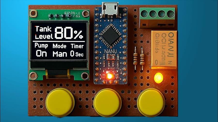
The Arduino Water Level Controller is an efficient automation system that monitors water tank levels and controls pumps automatically. This Arduino Water Level Controller tutorial explains the circuit, components, and wiring in detail. The Arduino Water Level Controller uses a relay to control the pump and an OLED display to show tank status. With the Arduino Water Level Controller, you can prevent overflow, dry running, and water wastage.
This guide covers how to assemble, wire, and program your Arduino Water Level Controller step-by-step. The Arduino Water Level Controller is suitable for homes, farms, and industrial setups. This beginner-friendly Arduino Water Level Controller project requires basic tools and affordable components. Learn to build your own Arduino Water Level Controller today for reliable, hands-free water management.
1. Introduction
Water wastage from overflowing tanks and pump dry-running are two common problems in both households and industrial setups. Having worked on automation projects for over a decade, I can tell you that a well-built Arduino Water Level Controller is one of the simplest yet most effective solutions.
This project uses an Arduino Nano, an OLED display, a relay module, and basic electronic components to monitor water levels and automatically control a pump. You’ll see tank status on the OLED screen and enjoy fully automated pump switching—no more manual checks or forgetting to turn the pump off.
2. How It Works
Level Sensing: The system detects water levels via probes or float switches connected to the Arduino.
Signal Processing: The Arduino reads these inputs and decides whether to activate the pump.
Relay Control: A 5V relay switches the pump motor on or off.
OLED Display: Real-time water levels and pump status are displayed for quick monitoring.
When the water drops below the minimum level, the pump starts. Once it reaches the maximum level, the pump stops—all automatically.
3. Materials for the Project
| Component | Qty | Description |
|---|---|---|
| Arduino Nano Click & Buy | 1 | Main controller board |
| OLED Display (0.96″ I2C) Click & Buy | 1 | Displays water level & status |
| LED Click & Buy | 1 | Status indication |
| BC547 Transistor Click & Buy | 1 | Relay driver |
| 1N4148 Diode Click & Buy | 1 | Flyback protection |
| 100 Ω Resistor Click & Buy | 1 | LED current limiting |
| 1K Resistor Click & Buy | 1 | Transistor base resistor |
| 5V Relay Module Click & Buy | 1 | Controls pump motor |
| 2-Pin Terminal Block Click & Buy | 2 | Wiring connection points |
| Perf Board Click & Buy | 1 | Circuit assembly |
| Jumper Wires Click & Buy | As req. | Circuit connections |
Useful Tools:
| Tool Name | Purpose/Usage |
|---|---|
| Electronic Tool Kit | Basic assembly, wiring, and testing |
| Hardware Tool Kit | Mounting, drilling, and mechanical adjustments |
| Desktop Oscilloscope | Signal monitoring and troubleshooting |
| Hand-held Oscilloscope | Portable signal testing on-site |
| Cordless Drill and Screwdriver | Drilling and fastening components |
| Power Supply | Providing stable voltage during testing |
| Soldering Station | Soldering components to perf board or PCB |
| Drill Press | Accurate hole drilling in enclosures |
| 3D Printer | Making custom enclosures or mounts |
| CNC Machine | Precision cutting and fabrication |
Download Circuit Diagram
4. Circuit Diagram Explanation
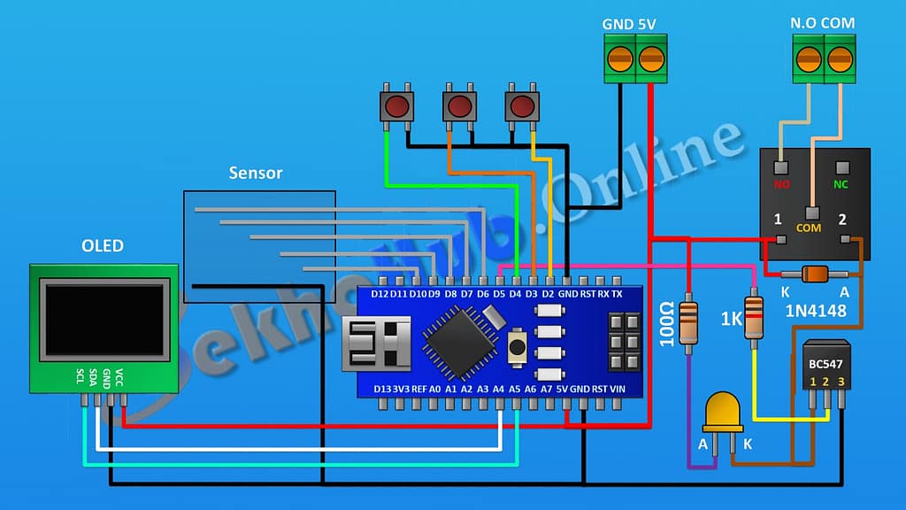
The Arduino Water Level Controller circuit connects level sensors (float switches or conductive probes) to the Arduino Nano’s digital inputs. The OLED display uses I2C communication (SDA, SCL).
The BC547 transistor acts as a driver for the relay coil, allowing the low-current Arduino output to control the high-current pump. The 1N4148 diode across the relay coil protects against voltage spikes (flyback).
The LED gives a visual indication when the pump is active. The relay output terminals connect directly to the pump motor circuit.
5. Step-by-Step Build Guide
Step 1.
- First connect Arduino.
Step 2.
- The OLED display connects via the I2C port to Arduino. Its VCC pin connects to the 5-fold pin of Arduino. its SDA pin to A4 pin of Arduino its SCL pin to the A5 pin of the Arduino and its ground pin to the ground pin on the Arduino.
Step 3.
- Then we connect three push buttons and connect their one pin to pins D2, D3, and D4 of the Arduino and connect their remaining pins to ground.
Step 4.
- Then connect a BC547 transistor and connect its pin number three to ground.
Step 5.
- now connect a 1k resistor and connect its one pin to D5 pin on Arduino and its other pin to pin number two of
the transistor.
Step 6.
- Now connect the 5V relay and connect its one coil pin to the 5V pin on the Arduino and its other coil pin to pin number one of the transistor.
Step 7.
- Now connect the 1N4148 diode and connect its cathode to the 5V supply and its anode to pin number one of the transistor.
Step 8.
- Now connect an LED and connect its cathode to pin number one of the transistor.
Step 9.
- Now connect a 100-ohm resistor and connect its one pin to the 5V supply and its other pin to the anode of the LED.
Step 10.
- Now connect a two-pin terminal block and connect its one pin to the 5-fold pin on the Arduino and its other pin to ground.
Step 11.
- now connect another two-pin terminal block and connect its one pin to common terminal of relay and its
other pin to normally open terminal of
the relay.
Step 12.
- Now let’s connect the water level sensor, which consists of six conductive wires connected to Arduino’s pins D6, D7, D8, D9, D10, and the common wire connected to the ground, so we have completed all the connections, and our circuit is completed.
Step 13.
- Now let’s upload this code to Arduino and test the project.
6. Applications
Domestic overhead tank automation
Agricultural irrigation systems
Industrial water reservoir control
Rainwater harvesting automation
7. FAQs
Q1: Can I use an ESP32 instead of an Arduino Nano?
Yes, especially if you want IoT features like Wi-Fi monitoring.
Q2: Can I replace the OLED with an LCD?
Yes, but OLEDs offer better visibility and require fewer pins.
Q3: How long will the sensors last in water?
Float switches last years, but conductive probes may corrode—use stainless steel for longevity.
Q4: Is isolation needed for safety?
Yes, always isolate control circuits from pump mains with proper relay modules.