

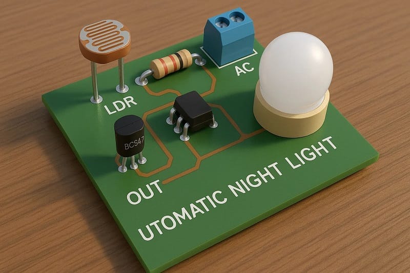
DIY Automatic Night Light with LDR & BC547 (LED + Optional Relay)
Learn how to make a DIY automatic night light that switches on when it’s dark and off when it’s bright. This DIY automatic night light uses a simple LDR and BC547 transistor circuit to control an LED or relay for AC loads. Our step-by-step guide makes building a DIY automatic night light quick and beginner-friendly, requiring only a few low-cost components. Whether you want a DIY automatic night light for your bedroom, garden, or hallway, this project offers a reliable and energy-saving solution.
The DIY Automatic Night Light design is easy to customize, allowing you to adjust sensitivity and load capacity. You’ll get a complete bill of materials, a detailed circuit diagram, and clear assembly instructions so you can finish your DIY Automatic Night Light in under 30 minutes. Perfect for hobbyists, students, and electronics enthusiasts.
What you’ll build
A light that turns on automatically at dusk and off at dawn.
Two variants:
Low-power LED version (5–12 V supply).
Relay version to switch higher loads (e.g., a 220 V AC bulb) through proper isolation.
Materials for the Project (DIY Automatic Night Light)
An LDR (light-dependent resistor) and a fixed resistor/potentiometer form a voltage divider that changes voltage with ambient light.
A BC547 NPN transistor senses that divider voltage:
Dark → higher base voltage → transistor turns ON → LED (or relay) energizes.
Bright → lower base voltage → transistor turns OFF → LED (or relay) de-energizes.
A trimpot lets you set the exact “turn-on” light level.
Useful Tools
| Tool | Quantity | Purpose / Notes | Click & Buy |
|---|---|---|---|
| Soldering Iron Kit | 1 | For making permanent connections | Click & Buy |
| Solder Wire (60/40, 0.8mm) | 1 | Electrical soldering | Click & Buy |
| Wire Stripper & Cutter | 1 | Stripping jumper wires | Click & Buy |
| Mini Screwdriver Set | 1 | For module and relay terminal screws | Click & Buy |
| Multimeter | 1 | Testing voltages and continuity | Click & Buy |
| Hot Glue Gun (optional) | 1 | Securing components in place | Click & Buy |
| Small Pliers | 1 | Holding and bending wires | Click & Buy |
| Heat Shrink Tubing Set | 1 | Insulating exposed wires | Click & Buy |
Bill of Materials (Automatic Night Light)
Common parts (both versions)
1× LDR (5–10 mm, typical dark/light resistance 100 kΩ/10 kΩ)
1× BC547 (or 2N2222, S8050—any small-signal NPN)
1× 100 kΩ trimpot (or 50–100 kΩ; sets sensitivity/threshold)
1× 47 kΩ resistor (base bias / with the pot, see wiring)
1 × 10 kΩ resistor (pull-down; stabilizes base)
1× Power supply: 5–12 V DC (adapter or battery)
Breadboard or PCB, jumper wires
LED version add-ons
1× LED (any color)
1× 330 Ω resistor for 5 V (use 680–1 kΩ for 9–12 V)
Relay version add-ons
1× 5 V relay module (opto-isolated preferred) or bare 5 V relay + driver parts below
If using a bare relay, also add:1× 1N4148/1N4007 diode (flyback across relay coil)
1× 1 kΩ resistor (base resistor for a dedicated driver transistor)
1× 2N2222/BC337 (relay driver transistor, more coil current)
Terminal block for AC load wiring (if switching mains)
Enclosure (for safety)
Safety first: If you switch mains (220–240 VAC), keep low voltage and mains well isolated. Use a proper relay module/enclosure, strain relief, and heat-shrink. Never touch live wiring while powered.
Circuit diagram (text description & pin mapping)
LED version (simple)
Supply: 5 V (works up to 12 V with resistor changes)
Voltage divider/sensor:
One leg of LDR → +V (5–12 V)
Other leg of LDR → Wiper of 100 k pot
Pot end-1 → GND
Pot end-2 → +V (this makes it a variable divider with the LDR)
From the wiper, also go through 47 kΩ to BC547 base
10 kΩ from base → GND (base pull-down for stability)
Transistor stage (BC547):
Emitter → GND
Collector → LED (anode)
LED (cathode) → series resistor (330 Ω @ 5 V) → +V
LED lights when it’s dark. If it’s inverted (lights in bright light), swap LDR position so the divider swings the other way, or rotate the pot range.
Relay version (recommended using a relay module)
Keep the sensor & BC547 portion the same as above.
Instead of LED load:
Use the BC547 to drive a second transistor (e.g., 2N2222) that drives the relay coil, or just feed the BC547 output into a ready-made relay module’s IN pin (simplest).
If a bare relay:
2N2222 emitter → GND
2N2222 collector → one side of relay coil
Other side of coil → +5 V
Flyback diode across coil (cathode at +5 V, anode at transistor collector)
1 kΩ base resistor from BC547 collector (or directly from divider if you skip BC547) to 2N2222 base
Load wiring (mains): Use COM and NO on the relay to switch your AC bulb. Keep all main wiring isolated and enclosed.
Quick design math (so you can tweak confidently)
LED resistor (5 V example)
Typical LED drop ≈ 2.0 V @ 10 mA →
R=5V−2V10mA=300ΩR = \frac{5V – 2V}{10mA} = 300Ω → Use 330 Ω (standard).For 9 V: R=9−210mA≈700ΩR = \frac{9-2}{10mA} ≈ 700Ω → 680–1 kΩ is fine.
For 12 V: R≈12−210mA=1kΩR ≈ \frac{12-2}{10mA} = 1kΩ. Use 1 kΩ.
Base current sanity (BC547 switching LED)
Collector current (LED) ≈ 10 mA.
With h_FE(sat) ≈ 10 for safe saturation, base current ≈ 1 mA.
With 47 kΩ from the divider and a threshold about ~0.7 V above the base-emitter, the pot sets the divider to source ~1 mA in darkness peaks—good enough for switching. If your LED is dim, lower the 47 kΩ to 33 kΩ.
LDR divider behavior
LDR typical: ~10 kΩ (bright), ~100 kΩ (dark).
The 100 k pot lets you move the base threshold so the circuit triggers at your desired room light level.
Download Circuit Diagram

Step-by-step build (LED version)
Power rails: Bring +5 V and GND to your breadboard.
Place the LDR:Connect one leg to +5 V and the other to a middle bus (call it “sense node”).
Add the 100 k pot:
Pot end-1 → GND, end-2 → +5 V, wiper → sense node.
Bias network:
47 kΩ from sense node → BC547 base.
10 kΩ from base → GND.
Transistor & LED:
BC547 emitter → GND.
BC547 collector → LED anode.
LED cathode → 330 Ω → +5 V. (Yes, LED to +V through resistor; collector sinks current when ON.)
Power up with 5 V.
Tune: Rotate the pot until the LED just turns OFF in bright light and ON in shadow. Fine-tune for dusk response.
Download Circuit Diagram

Step-by-step build (Relay version, with a relay module)
Build steps 1–4 from the LED version (sensor & bias are identical).
Replace the LED load with a relay module:
Keep BC547 emitter → GND.
BC547 collector → module IN (Many modules trigger LOW; check your module’s logic).
Module VCC → +5 V, module GND → GND.
Test the click:Shade the LDR—the relay should click.
AC wiring: With power disconnected, wire AC live through COM–NO to your bulb. Close the enclosure, then power up and test.
If your relay module expects an active-HIGH signal but your collector only sinks, you can wire IN to the base via a suitable 1–4.7 kΩ resistor and pull IN down with 10 kΩ to GND, or invert in hardware with a second transistor stage. Many common modules are active-LOW, which pairs nicely with an NPN sinking output.
Tuning & troubleshooting
LED is always ON:
Reduce ambient light on the LDR (cup your hand), then rotate the pot toward the position that turns it off. If still stuck, swap the LDR and pot positions in the divider or increase the base pull-down (try 6.8 kΩ–15 kΩ).LED never turns ON in the dark:
Lower the 47 kΩ to 33 kΩ or even 22 kΩ to give the base more drive, or use a more sensitive LDR.Relay chatters around threshold:
Add a little hysteresis: a 470 kΩ–1 MΩ resistor from collector to base (positive feedback) so once it turns ON, it stays on until it gets clearly brighter.False triggers from room lights flicker:
Add a 0.1–1 µF capacitor from base → GND (with the 10 kΩ) to make a small RC filter.Outdoor use:
Put the LDR behind a clear weatherproof window; keep electronics inside a sealed box. Consider a TVS diode or RC snubber for surge protection if switching inductive loads.
Variations & upgrades
Brightness-based dimming: Replace the on/off LED with a MOSFET (e.g., IRLZ44N) and drive a strip; add PWM (needs a small MCU).
Solar garden lamp upgrade: Use this trigger to enable a DC-DC boost that powers LEDs only at night.
Two-point control: Add a second trimpot and comparator (LM393) for crisp thresholds and built-in hysteresis without feedback tricks.
Quick wiring table (LED version)
| Node | Connects To |
|---|---|
| +V (5–12 V) | LDR leg-1, Pot end-2, LED resistor (to LED cathode) |
| GND | Pot end-1, BC547 emitter, 10 kΩ base pull-down |
| Sense node | LDR leg-2, Pot wiper, 47 kΩ → BC547 base |
| BC547 collector | LED anode |
| LED cathode | Series resistor → +V |
FAQ
Q1: Can I run it at 12 V?
Yes. Use a 1 kΩ LED resistor. For relay, use a 12 V relay/module and keep the sensing network the same (pot/LDR values still work).
Q2: My relay module triggers opposite (ON in bright light).
Swap the divider’s top/bottom (put the LDR to GND instead of +V) or invert with a second transistor. You can also retune the pot (sometimes enough).
Q3: Can I power it from a phone charger?
Yes, a 5 V USB adapter works perfectly.
Q4: What LDR size is best?
5–10 mm standard photoresistors are fine. Just pick one with ~10 kΩ in bright light and >50–100 kΩ in darkness.
Q5: How do I add hysteresis neatly?
Add 680 kΩ from collector to base. Start there; adjust between 470 kΩ and 1 MΩ as needed.
Q6: Is an LM393 comparator better?
For sharp switching, yes. This transistor version is minimal and works great; LM393 adds precision and built-in hysteresis with a couple of resistors.
Q7: Can I switch a fan or charger (inductive loads)?
Yes, with a proper relay module and flyback diode (if a bare relay). For heavy inductive loads, use a relay with adequate contact rating and consider an RC snubber across the load.
Quick notes if you document this on your site
Add a schematic image with clear labels: LDR–pot divider to base, LED to collector, and resistor to +V.
Include a tuning section (pot direction and ambient examples).
Show two builds: a breadboard first, then a small perfboard in an enclosure.
If you add the relay variant, emphasize mains isolation and enclosure photos.