
The 3-in-1 AC Meter project allows hobbyists and engineers to measure AC voltage, current, and power using an Arduino. This device combines multiple functionalities into a single Arduino meter display, enabling real-time monitoring of electrical parameters safely and accurately. Ideal for home or industrial applications, this project helps users understand energy consumption and troubleshoot electrical issues. With simple components and a well-structured Arduino AC voltage monitor setup, it is accessible even for beginners looking to explore Arduino-based electrical measurement techniques in a hands-on way.
Overview
The 3-in-1 AC Meter uses a combination of an Arduino, current transformer Arduino, and an OLED display Arduino meter to provide real-time readings of AC voltage, current, and power. By integrating Arduino power measurement functionality with safe sensing circuits, the system delivers accurate data for both small and medium loads. The meter monitors AC mains in real time, calculates the power factor, and logs electrical parameters for further analysis. With a compact design and a step-by-step Arduino AC project approach, it is perfect for students, hobbyists, and professionals seeking a versatile electrical measurement tool.
Video Tutorial
Materials for the Project
| Component | Quantity | Description / Purpose | Buy Link |
|---|---|---|---|
| Arduino Nano | 1 | Main microcontroller to sample, process, and display measurements | Buy Link |
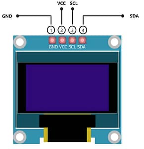
| OLED Display (0.96″, SSD1306, I²C) | 1 | 128×64 screen to show Voltage, Current, Power, PF | Buy Link |
| Current Transformer 100 A / 50 mA (2000:1) | 1 | Isolated current sensing of AC load | Buy Link |
| LM358 IC | 1 | Dual op-amp for signal conditioning & biasing | Buy Link |
| 47 Ω Resistor (1%) | 1 | CT burden resistor | Buy Link |
| 2.2 kΩ Resistor (1%) | 1 | Voltage divider (bottom leg) | Buy Link |
| 4.7 kΩ Resistor (1%) | 1 | Voltage divider (bottom leg) | Buy Link |
| 10 kΩ Resistors (1%) | 3 | Mid-rail bias network, pull-downs | Buy Link |
| 470 kΩ Resistors (1%) | 6 | High-voltage divider chain (scales mains voltage) | Buy Link |
| 2-pin Terminal Blocks | 2 | One for AC input, one for CT secondary | Buy Link |
| Perfboard | 1 | For assembling the circuit | Buy Link |
| Jumper wires | — | Connections between components | Buy Link |
Arduino.
The Arduino Nano is a compact microcontroller that samples, processes, and displays AC voltage, current, and power readings. It supports real-time Arduino energy meter circuit operations with an OLED display for live monitoring. Its small form factor makes it ideal for compact Arduino AC meter projects. Learn more.
Download Circuit Diagram

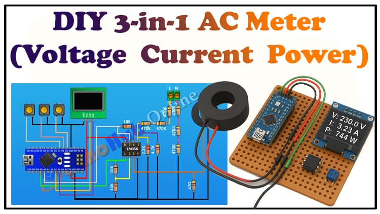
The circuit diagram integrates the Arduino, current transformer Arduino, and voltage divider network. The CT measures current, the high-voltage divider scales mains voltage, and the LM358 op-amp conditions the signals before sending them to the Arduino analog pins. The OLED display Arduino meter shows real-time voltage, current, and power readings.
How the Circuit Works ?
Voltage Sensing & Scaling
- Goal: Convert 230 VAC (≈325 Vpk) to a small, safe waveform for the ADC.
- Divider idea: Six 470 kΩ in series form ~2.82 MΩ on the top leg. The bottom leg uses 4.7 kΩ + 2.2 kΩ = 6.9 kΩ to ground.
- Approx. ratio: 2.82 MΩ : 6.9 kΩ ≈ 409:1.
- Peak at ADC (pre-bias) ≈ 325 V / 409 ≈ 0.79 Vpk (≈0.56 Vrms). Perfect headroom for conditioning.
- RC filter: Place ~100 nF film cap across the bottom leg to reduce HF noise; keep the time constant short enough to preserve the 50/60 Hz shape.
- Protection: Add 220 Ω series + 5 V TVS near the MCU pin. Always include a fuse and MOV on the line side, and enforce creepage/clearance.
Isolation note: This divider is not isolated. The CT provides isolation for current, but voltage scaling here is live-referenced. Use an isolated AC transformer if you require full galvanic isolation for voltage.

Current Sensing with CT (100 A/50 mA, 2000:1)
- CT principle: Primary current induces a scaled secondary current (50 mA at 100 A primary).
- Burden resistor (47 Ω): Converts secondary current to voltage. At 50 mA RMS, Vburden ≈ 0.05 A × 47 Ω ≈ 2.35 Vrms (≈3.32 Vpk). That’s a healthy signal that we’ll attenuate/condition before the ADC.
- RC filtering: 100 nF across burden tamps HF spikes. Keep CT leads twisted; avoid open-circuiting a powered CT (large voltages can develop).

Mid-Rail Bias & LM358 Conditioning
- The Arduino’s ADC reads 0–5 V. We bias signals around Vref/2 ≈ 2.5 V using two 10 kΩ resistors (5 V–2.5 V–GND) and decouple with 10 µF.
- LM358 (two channels):
- Voltage channel: Buffer the divided mains waveform and shift it around 2.5 V (AC-couple through a cap to the 2.5 V rail, then buffer). Optional small gain (<×2) if needed.
- Current channel: First attenuate the CT burden voltage if necessary (simple divider), then AC-couple to the 2.5 V bias and buffer. Optionally add a small anti-alias RC at the output.
- Outputs go through 220 Ω into A0 (voltage) and A1 (current).
Display
- Use an I²C OLED (SSD1306). Show:
- Line 1: Vrms (e.g., 229.7 V)
- Line 2: Irms (e.g., 4.12 A)
- Line 3: Real Power (e.g., 945 W)
- Line 4: PF (e.g., 0.96 lag)
Step-by-Step Build Guide (3-in-1 AC Meter)
Step 1
First connect Arduino.
Step 2
Then connect LM358 IC. And connect its pin number one to A0 pin of Arduino. Its pin number two to A7 pin of Arduino. Its pin number eight to 5V pin of Arduino And its pin number four to ground.
Step 3
Now connect a 10k resistor and connect its one pin to pin number one of the IC and its other pin to pin number two of the IC.
Step 4
Now connect another 10k resistor and connect its one pin to pin number two of the IC and its other pin to ground.
Step 5
Now connect 47 ohm resistor and connect its one pin to pin number three of the IC and its other pin to ground.
Step 6
Now connect the current transformer and connect its one pin to pin number three of the IC and its other pin to ground.
Step 7
Now connect a 10k resistor and connect its one pin to pin number seven of the IC and its other pin to pin number six of the IC.
Step 8
Now connect a 4.7K resistor and connect its one pin to pin number six of the IC and its other pin to ground.
Step 9
Now connect a 2.2k 2k resistor and connect its one pin to pin number five of the IC and its other pin to ground.
Step 10
Now connect a two pin terminal block.
Step 11
Now connect a 470k resistor and connect its one pin to pin
number five of the IC.
Step 12
Now connect another 470k resistor and connect its one pin to remaining pin of the previous 470k resistor.
Step 13
Now connect another 470k resistor and connect its one pin to remaining pin of the 470k resistor and its other pin to pin number one of the two pin terminal block.
Step 14
Now connect another 470k resistor and connect its one pin to ground.
Step 15
Now connect another 470k resistor and connect its one pin to previous 470k resistor.
Step 16
Now connect another 470k resistor and connect its one pin to remaining pin of the previous 470k resistor and its other pin to pin number two of the two pin terminal block.
Step 17
Now connect the OLED display and connect its VCC pin to 5 volt pin of Arduino. Its ground pin to ground its SDA pin to A4 pin of Arduino and its Sccl pin to A5 pin of Arduino.
Step 18
Now connect a push button and connect its one pin to pin D2 of Arduino and its other pin to ground.
Step 19
Now connect another push button and connect its one pin to pin D3 of Arduino and its other pin to ground.
Step 20
Now connect another push button and connect its one pin to D4 pin of Arduino and its other pin to ground. So we have completed all the connections.
Step 21
Now let’s upload the code to Arduino and test the project.
Arduino Code
Applications
Home energy consumption monitoring
Industrial load measurement
Power factor analysis
Educational electronics projects
DIY 3-in-1 electrical meter experiments
FAQs
Can Arduino measure AC?
Yes, with a current transformer Arduino and voltage divider, Arduino can measure AC safely.
Is Arduino due 5V or 3.3V?
Most Arduino Nano boards run at 5V logic; some models support 3.3V.
Can an Arduino be used as a multimeter?
Yes, it can measure AC voltage, current, and power, acting as a basic digital meter.
How to measure 230V AC with Arduino?
Use a high-voltage divider chain and isolation through a current transformer Arduino.
Can Arduino supply AC?
No, Arduino outputs only DC voltage; AC measurement requires external sensing.
What is the maximum voltage for 230V AC?
The nominal voltage is 230V RMS; peaks can reach ~325V.
Conclusion
The 3-in-1 AC Meter Using Arduino is an effective tool for measuring voltage, current, and power safely. With a simple Arduino energy meter circuit, this project is ideal for DIY electronics enthusiasts, educational purposes, and real-time electrical monitoring. Integrating a current transformer Arduino and OLED display Arduino meter ensures accurate and readable outputs while keeping the system compact and efficient.
Related Posts
Arduino Energy Meter Project
Arduino AC Voltage Monitoring
Step-by-Step Arduino Current Sensor Projects
DIY Power Factor Meter Using Arduino