

All Components Tester (No MCU) | 9 Proven Checks for Components
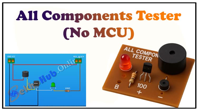
This article explains how to build an All Components Tester (No MCU) using just one BC547 transistor, an LED, a 100 Ω resistor, and a buzzer or 9V battery. The All Components Tester (No MCU) can check transistors, MOSFETs, IGBTs, capacitors, diodes, resistors, and continuity in a single setup. If you are an electronics hobbyist or technician, an All Components Tester (No MCU) is one of the most practical tools you can build at home.
This All Components Tester (No MCU) is simple, reliable, and highly cost-effective, making it an excellent project for beginners. Unlike digital testers, the All Components Tester (No MCU) works without any microcontroller and provides instant results. Learn step-by-step how to assemble and use your All Components Tester (No MCU) effectively. Build this All Components Tester (No MCU) to simplify your electronics projects today.
9 Essential Functions in One: A Powerful All Components Tester (No MCU)
As an electronics engineer with over a decade of hands-on experience, I often tell my students and colleagues: the best tools are usually the simplest ones.
That’s why today, we’re building an All Components Tester (No MCU) — a compact tester that requires only four basic components:
- 1 × BC547 transistor
- 1 × LED
- 1 × 100 Ω resistor
- 1 × buzzer or 9V battery
Despite its simplicity, this tester can handle 9 different practical tests in electronics.
Why Build an All Components Tester (No MCU)?
Modern testers with microcontrollers and LCD screens are useful, but they’re not always necessary. Sometimes you need a quick, reliable, and portable tool to check if a component is working.
The All Components Tester (No MCU) is:
- Low-cost — only a handful of components.
- No programming required — works directly with discrete parts.
- Versatile — capable of testing diodes, capacitors, MOSFETs, IGBTs, BJTs, and more.
- Beginner-friendly — easy to assemble on a breadboard or perf board.
Materials for the Project
| S.No | Component | Value/Part Number | Quantity | Buy Link |
|---|---|---|---|---|
| 1 | NPN Transistor | BC547 | 1 × | Buy Link |
| 2 | LED | 5mm Red LED | 1 × | Buy Link |
| 3 | Resistor | 100 Ω (¼ Watt) | 1 × | Buy Link |
| 4 | Buzzer | 5V/9V Piezo Buzzer | 1 × | Buy Link |
| 5 | Battery | 9V Battery + Clip | 1 × | Buy Link |
| 6 | Breadboard / PCB | General Purpose Board | 1 × | Buy Link |
| 7 | Jumper Wires | Male-to-Male | As Needed | Buy Link |
Download Circuit Diagram

Circuit Diagram Explanation
The circuit is very straightforward:
- The BC547 transistor works as a switch and amplifier.
- The LED with the 100 Ω resistor indicates test results visually.
- The buzzer (or 9V battery) provides an audible signal for continuity and short testing.
- When you connect a diode in forward bias, current flows → LED glows.
- When a capacitor is connected, you’ll see LED charging and discharging.
- For transistors, the BC547 acts as a reference, allowing you to test base-emitter and collector-emitter junctions.
Step-by-Step Guide
Step 1: Assemble the Power Source
- Connect your 9V battery or buzzer supply to the breadboard.
- Positive terminal → resistor → LED → BC547 collector.
- Negative terminal → BC547 emitter.
Step 2: Connect the LED and Resistor
- Place the 100 Ω resistor in series with the LED.
- This protects the LED from excessive current.
Step 3: Insert the BC547 Transistor
- Connect the emitter to ground (negative terminal).
- Connect the collector through the LED + resistor to positive.
- Base will act as the input test terminal.
Step 4: Add the Test Points
- Provide three connection pins:
- Positive Test Pin
- Negative Test Pin
- Base/Control Pin
Step 5: Testing Components
Here’s how you can test different components:
1. Diodes
- Forward bias → LED glows.
- Reverse bias → LED off.
2. Capacitors
- Connect across terminals.
- LED flashes briefly while charging → then goes off.
- Reverse leads → LED discharges briefly.
3. BJTs (Transistors)
- Use base as test input.
- Forward bias base-emitter → LED lights when collector connected.
- Reverse → no light.
4. MOSFETs & IGBTs
- Apply small gate charge.
- Check drain-source conduction with LED indicator.
5. Resistors
- Low-value resistors → LED glows.
- High-value resistors → LED dim or off.
6. Continuity Tester
- Short the terminals.
- LED glows + buzzer sounds.
7. LEDs
- Connect like a diode.
- If it glows, it’s functional.
8. Short-Circuit Detection
- If terminals are directly shorted → LED + buzzer on continuously.
9. Polarity Testing
- Capacitors and diodes can be identified for correct polarity.
Real-Life Example
Imagine you’re repairing a power supply and suspect the rectifier diodes are faulty. Instead of pulling out your multimeter, you connect them to the All Components Tester (No MCU).
- Good diode → LED glows one way only.
- Faulty diode → LED glows both ways (short) or not at all (open).
In just 2 seconds, you know the result.
Advantages of This Tester
- Ultra-low cost (under $2).
- Portable — fits in your pocket.
- No coding required — pure hardware.
- Multiple uses — replaces several tools.
- Beginner-friendly — ideal for students and DIYers.
Limitations
- Cannot measure exact resistance/capacitance values.
- Only checks if component is working, not precise parameters.
- Not suitable for SMD parts unless adapted with clips.
FAQs
Q1: Can this tester replace a digital multimeter?
Not entirely. A multimeter provides precise measurements, while this tester gives quick functional checks.
Q2: Can I use another transistor instead of BC547?
Yes, any general-purpose NPN transistor like 2N2222 will work.
Q3: What’s the maximum capacitor rating I can test?
This circuit is good for electrolytic capacitors up to 1000 µF. Larger values may require longer charge times.
Q4: Does this tester work for SMD components?
Yes, but you’ll need fine test probes or clips.
Q5: Can I add more indicators?
You can connect multiple LEDs of different colors for polarity or status indication.