

ESP32 8 Channel Wi-Fi Relay | 7 Powerful Steps to Build an ESP32 Automation Project
The ESP32 8 Channel Wi-Fi Relay is a practical and low-cost automation project for controlling up to 8 electrical devices wirelessly. This ESP32 automation project is designed with simple components including an ESP32 Dev Board, ULN2803 relay driver, 8 relays, LEDs, and an OLED display. The system allows real-time monitoring and control through Wi-Fi, making it ideal for home automation, greenhouse monitoring, water pump control, HVAC systems, and industrial machine control.
This guide provides a full circuit explanation, a detailed BOM list, and step-by-step instructions for wiring and programming. The OLED screen displays the live status of each relay, while push buttons allow manual switching alongside web-based control. With built-in Wi-Fi capability, the ESP32 connects directly to a router for remote operation without extra hardware. This project is reliable, expandable, and perfect for DIY IoT automation.
Introduction
Automation has become a central part of both homes and industries. With IoT (Internet of Things), it’s now possible to control lights, fans, pumps, and even machines directly from a smartphone. Instead of buying expensive commercial modules, you can create your own ESP32 8 Channel Wi-Fi Relay system an ESP32 automation project that combines low-cost hardware with versatile software.
This DIY controller allows you to control 8 independent relays through Wi-Fi. Each relay can switch an AC or DC load, making it useful for:
Smart home lighting
HVAC (heating, ventilation, air conditioning)
Water pumps and irrigation
Greenhouse automation
Industrial equipment control
In this article, I’ll show you the components, circuit diagram, build steps, and code to bring this project to life.
Materials for the Project (ESP32 8 Channel Wi-Fi Relay)
| Component | Quantity | Purpose | Buy Link |
|---|---|---|---|
| ESP32 Dev Board | 1 | Main Wi-Fi + controller MCU | Buy ESP32 |
| SSD1306 OLED Display (128×64 I2C) | 1 | Displays relay status | Buy OLED Display |
| Yellow LEDs | 8 | Relay ON/OFF indicators | Buy LEDs |
| Push Buttons | 3 | Manual control / reset / mode | Buy Push Buttons |
| ULN2803 IC | 1 | Relay driver IC (8-channel Darlington array) | Buy ULN2803 |
| 5V Relays | 8 | Controls AC/DC loads | Buy 5V Relay |
| 100Ω Resistors | 8 | Current limiting for LEDs | Buy Resistors |
| 5V DC Power Supply | 1 | Powers ESP32 + relays | Buy 5V Power Supply |
| 2-Pin Terminal Block | 1 | Power input connector | Buy Terminal Blocks |
| 3-Pin Terminal Blocks | 8 | Relay outputs (COM, NO, NC) | Buy Terminal Blocks |
| Jumper Wires | — | Wiring connections | Buy Jumper Wires |
You can get datasheets and more details here:
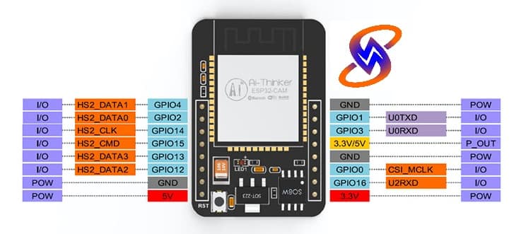
ESP32 Pinout
Gerber Files
⚡ Circuit Diagram Explanation (ESP32 8 Channel Wi-Fi Relay)
The wiring is straightforward but requires attention to safety:
ESP32 to ULN2803
GPIO pins from the ESP32 are connected to the input pins of the ULN2803 IC.
ULN2803 outputs drive the relay coils.
Relay Connections
Each relay is connected to a 3-pin terminal block (COM, NO, NC).
This allows external AC/DC loads to be switched safely.
LED Indicators
Each relay channel has a yellow LED + 100Ω resistor connected to indicate ON/OFF status.
OLED Display
Connected via I2C: SDA → GPIO 21, SCL → GPIO 22.
Displays relay status and system messages.
Push Buttons
Button 1 → Manual ON/OFF toggle
Button 2 → Reset ESP32
Button 3 → Auto/Manual mode switch
Power Supply
A regulated 5V DC supply powers the ESP32, relays, ULN2803, and OLED.
Step-by-Step Build Guide (ESP32 8 Channel Wi-Fi Relay)
Step 1: Power Setup
Connect the 5V supply to the ESP32 and relay circuits via the terminal block.
Step 2: Relay Driver Wiring
ESP32 GPIOs → ULN2803 Inputs
ULN2803 Outputs → Relay IN pins
Step 3: LED Indicators
Relay outputs → Yellow LED + 100Ω resistor → GND
Step 4: OLED Display
Connect SDA → GPIO 21
Connect SCL → GPIO 22
Step 5: Push Buttons
Each button connected between GPIO pin and GND.
Enable internal pull-ups in the ESP32 code.
Step 6: Install Arduino Libraries
Adafruit SSD1306
Adafruit GFX
WiFi.h (for ESP32)
Step 7: Upload Code
Flash the provided Arduino code onto the ESP32.
Connect to your Wi-Fi network.
Access the relay control panel via the ESP32 IP address.
Arduino Code Example (ESP32 8 Channel Wi-Fi Relay)
Here’s a simplified version (full version can be extended with MQTT/Home Assistant):
#include <WiFi.h>
#include <Adafruit_GFX.h>
#include <Adafruit_SSD1306.h>#define SCREEN_WIDTH 128
#define SCREEN_HEIGHT 64
Adafruit_SSD1306 display(SCREEN_WIDTH, SCREEN_HEIGHT, &Wire, -1);const char* ssid = “Your_SSID”;
const char* password = “Your_PASSWORD”;WiFiServer server(80);// Relay pins (ESP32 GPIOs)
int relayPins[8] = {5, 18, 19, 21, 22, 23, 25, 26};
bool relayState[8] = {0,0,0,0,0,0,0,0};void setup() {
Serial.begin(115200);
// Relay setup
for(int i=0; i<8; i++) {
pinMode(relayPins[i], OUTPUT);
digitalWrite(relayPins[i], HIGH); // OFF initially
}
// OLED init
if(!display.begin(SSD1306_SWITCHCAPVCC, 0x3C)) {
Serial.println(“SSD1306 allocation failed”);
for(;;);
}
display.clearDisplay();
display.setTextSize(1);
display.setTextColor(SSD1306_WHITE);
display.setCursor(0,0);
display.println(“ESP32 Relay Controller”);
display.display();
// Wi-Fi connection
WiFi.begin(ssid, password);
while (WiFi.status() != WL_CONNECTED) {
delay(500);
Serial.print(“.”);
}
Serial.println(“WiFi connected!”);
server.begin();
}
void loop() {
WiFiClient client = server.available();
if (!client) return;
String request = client.readStringUntil(‘r’);
client.flush();
// Relay control via URL
for(int i=0; i<8; i++) {
if(request.indexOf(“/relay”+String(i+1)+”on”) != -1) {
digitalWrite(relayPins[i], LOW);
relayState[i] = 1;
}
if(request.indexOf(“/relay”+String(i+1)+”off”) != -1) {
digitalWrite(relayPins[i], HIGH);
relayState[i] = 0;
}
}
// HTML page
client.println(“HTTP/1.1 200 OK”);
client.println(“Content-type:text/html”);
client.println();
client.println(“<html><h1>ESP32 Relay Control</h1>”);
for(int i=0; i<8; i++) {
client.println(“<p>Relay ” + String(i+1) + ” – State: ” + (relayState[i]?”ON”:”OFF”));
client.println(” <a href=”/relay”+String(i+1)+”on”>ON</a> “);
client.println(“<a href=”/relay”+String(i+1)+”off”>OFF</a></p>”);
}
client.println(“</html>”);
// OLED update
display.clearDisplay();
display.setCursor(0,0);
display.println(“Relay Status:”);
for(int i=0; i<8; i++) {
display.print(“R”);
display.print(i+1);
display.print(“: “);
display.println(relayState[i] ? “ON” : “OFF”);
}
display.display();
}
Applications
|  |
|  |
|  |
|  |
|  |
❓ FAQs
Q1: Can I control this from anywhere on the internet?
Yes, with port forwarding or MQTT you can access it remotely.
Q2: How much current can each relay handle?
Standard 5V relays support 10A at 250V AC or 30V DC.
Q3: Can I expand beyond 8 relays?
Yes, by using additional ULN2803 ICs and relays.
Q4: Is it safe to use with high voltage?
Yes, but ensure isolation and proper insulation when wiring AC loads.
Conclusion
This ESP32 8 Channel Wi-Fi Relay project is a powerful DIY automation solution. With just an ESP32, ULN2803, relays, LEDs, and an OLED display, you can create a smart system to control multiple devices over Wi-Fi.
It’s flexible, expandable, and integrates easily with smart home systems like Home Assistant or MQTT. Whether for home, greenhouse, or industrial use, this ESP32 automation project delivers reliable results at low cost.