

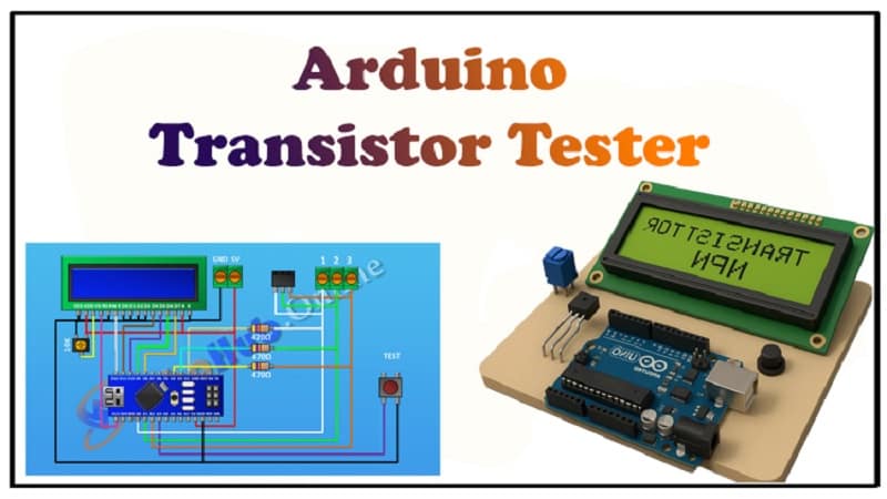
Arduino Transistor Tester With Code | 7 Step DIY Arduino Project
This Arduino Transistor Tester project helps electronics hobbyists and engineers test different transistors with ease. The Arduino Transistor Tester uses an Arduino Nano and a simple circuit to detect transistor type and pin configuration. In this guide, we will build the Arduino Transistor Tester step by step with full explanation, circuit diagram, and tested Arduino code. The Arduino Transistor Tester is reliable for NPN and PNP transistors, MOSFETs, and other components.
By using this Arduino Transistor Tester, you can easily check faulty transistors and learn how they function. This project is ideal for students, beginners, and professionals who need quick transistor identification. The Arduino Transistor Tester is designed using basic components, making it cost-effective. Build your own Arduino Transistor Tester today with simple coding and hardware. The Arduino Transistor Tester will make your lab projects easier and faster.
Introduction
Have you ever found a transistor lying around and had no clue whether it is NPN, PNP, or even functional? Manually checking with a multimeter can be time-consuming and tricky for beginners. That’s why today we are building a Precision Arduino Transistor Tester that automatically identifies transistors and their pin configuration.
This project uses controlled voltage signals, analog readings, and a smart algorithm to classify transistors with accuracy. Instead of trial and error, you’ll have instant results on an LCD display. It’s a great DIY project for electronics labs, hobbyists, and even students who want to understand semiconductor testing.
Video Tutorial
Materials for the Project
| Component | Quantity | Description / Notes | Buy Link |
|---|---|---|---|
| Arduino Nano | 1 | Main microcontroller board | Buy Here |
| 16×2 LCD Display | 1 | For showing transistor type & pinout | Buy Here |
| Push Button | 1 | To start the testing cycle | Buy Here |
| 470Ω Resistor | 3 | For base/gate biasing & current limiting | Buy Here |
| 10K Trimpot (Potentiometer) | 1 | For LCD contrast adjustment | Buy Here |
| 3-Pin Female Header | 1 | For inserting transistor under test | Buy Here |
| 2-Pin Terminal Block | 1 | Power input connection | Buy Here |
| 3-Pin Terminal Block | 1 | Alternate transistor test socket | Buy Here |
| Jumper Wires | As needed | For circuit connections | Buy Here |
Tip: If you want convenience, replace the 3-pin female header with a ZIF socket to insert and remove transistors easily.
Useful Tools
| Tool | Quantity | Purpose / Notes | Click & Buy |
|---|---|---|---|
| Soldering Iron Kit | 1 | For making permanent connections | Click & Buy |
| Solder Wire (60/40, 0.8mm) | 1 | Electrical soldering | Click & Buy |
| Wire Stripper & Cutter | 1 | Stripping jumper wires | Click & Buy |
| Mini Screwdriver Set | 1 | For module and relay terminal screws | Click & Buy |
| Multimeter | 1 | Testing voltages and continuity | Click & Buy |
| Hot Glue Gun (optional) | 1 | Securing components in place | Click & Buy |
| Small Pliers | 1 | Holding and bending wires | Click & Buy |
| Heat Shrink Tubing Set | 1 | Insulating exposed wires | Click & Buy |
Download Circuit Diagram
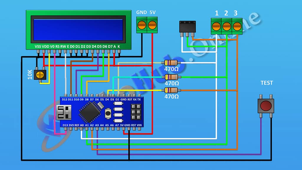
Circuit Diagram Explanation
The circuit uses Arduino Nano as the controller. A 16×2 LCD is connected in 4-bit mode to display the results. The push button initiates the test, and three 470Ω resistors help bias the transistor terminals safely during measurement.
- The 3-pin female header is connected to Arduino pins to allow the transistor under test (TUT) to be inserted in any order. The software algorithm will then check possible combinations.
- The 10K trimpot adjusts the contrast of the LCD.
- A push button connected to Arduino detects when the user wants to start testing.
Once the circuit is powered, the Arduino sends test pulses and reads the behavior at each terminal to determine:
- Whether the transistor is NPN or PNP.
- Which pin is Emitter, Base, Collector.
- If the transistor is faulty or not.
Step-by-Step Build Guide
Step 1.
The LCD screen connects to uino using.
Step 2.
Arduino’s digital pin from 8 to 13 add a 10K trim pod to adjust LCD brightness connecting its middle pin to LCD pin 3 and the other two to 5v and ground .
Step 3.
We use a three- pin terminal block to insert the transistor a female header is VI in parallel with it making it easy to use different transistor packages their pin one connects to arduino’s spin a0 pin 2 to arduino’s bin A1 pin 3 to arduino’s bin A2 this allows the Arduino to safely measure voltage levels .
Step 4.
we connect arduino’s spin D2 D3 and D4 two transistors spin 470 ohm resistors in series .
Step 5.
A push button is WI to arduino’s pin A3 which is digital pin 17 and ground pressing this button will trigger the transistor test sequence.
Step 6.
A two-pin terminal block is used for 5V power input ensuring a stable connection .
Step 7.
So we have completed all the connections now let’s upload the code and see it in.
Once uploaded, insert a transistor and press the button. The LCD will display whether it’s NPN/PNP and the pin configuration.
Arduino Code
Applications of Arduino Transistor Tester
- Quickly identifying unknown transistors.
- Checking faulty or dead transistors before use.
- Educational tool for electronics students.
- Useful for DIY electronics labs.
Advantages
- Low cost: Uses basic components.
- Time-saving: Automatically detects type and pinout.
- Portable: Small and can be powered via USB.
- User-friendly: LCD display makes results easy to read.
FAQs
Q1. Can this tester identify MOSFETs?
Yes, with improved code, MOSFETs and even IGBTs can be identified.
Q2. What is the maximum power rating supported?
This tester is designed for small signal transistors. High-power transistors may not be tested safely.
Q3. Can I use Arduino Uno instead of Nano?
Yes, the circuit and code work with Arduino Uno, Nano, or Mega.
Q4. Why use resistors in the test circuit?
To limit current and protect both the Arduino and the transistor under test.
Q5. Can I add a ZIF socket?
Yes, a ZIF socket makes it easier to test multiple transistors.
Final Words
Building an Arduino Transistor Tester is an excellent project for electronics enthusiasts. It not only makes testing transistors easy but also gives you hands-on experience with Arduino coding, analog measurements, and display interfacing. By extending the code, you can even test diodes, resistors, capacitors, and MOSFETs.
This project combines theory with practice—making it a must-have DIY tool for any electronics workspace.