

Zener Diode Tester Electronics Project | 7 Steps to Build It Easily
A Zener Diode Tester is an essential tool for electronics enthusiasts and engineers who often work with voltage regulation and circuit design. This Zener Diode Tester electronics project allows you to measure the breakdown voltage of different Zener diodes with ease. By building this Zener Diode Tester, you can test Zener diodes ranging from low to high voltages using a simple circuit powered by a 9V supply.
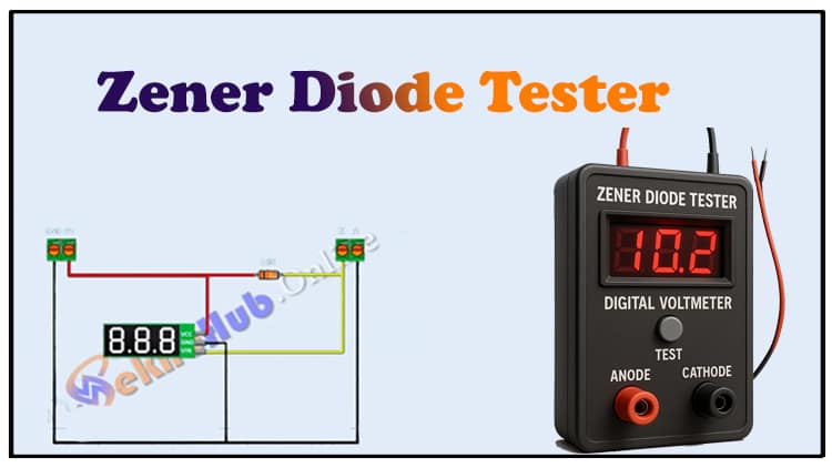
The Zener Diode Tester uses a digital voltmeter and a resistor to limit current while accurately displaying the Zener breakdown voltage. This Zener Diode Tester is compact, affordable, and ideal for hobbyists working on DIY projects. Whether you are a beginner or experienced in electronics, making your own Zener Diode Tester will help you understand Zener behavior and test components quickly. Build this Zener Diode Tester project today for your electronics lab.
Introduction
Every electronics hobbyist and engineer keeps a stock of Zener diodes for voltage regulation, protection, and reference purposes. However, Zener diodes often come unmarked, or their values may be uncertain when salvaged from old circuit boards. That’s where a Zener Diode Tester Electronics Project becomes very handy.
With just a 9V power source, a resistor, and a digital voltmeter, you can build a compact and reliable tester that allows you to measure the breakdown voltage (Vz) of Zener diodes. This DIY Zener Diode Tester helps you quickly identify diode ratings and ensures that your circuit designs remain accurate.
Materials for the Project
| Component | Quantity | Description | Buy Link |
|---|---|---|---|
| Zener Diode (various) | 1+ | For testing (3.3V, 5.1V, 12V, etc.) | Buy Link |
| Resistor 10kΩ (1/4W) | 1 | Current limiting resistor | Buy Link |
| 9V Battery | 1 | Power supply | Buy Link |
| 9V Battery Clip | 1 | For connecting battery | Buy Link |
| Digital Voltmeter (3-wire) | 1 | Displays Zener voltage | Buy Link |
| 2-Pin Terminal Blocks | 2 | For diode test connection | Buy Link |
| Perf Board | 1 | To mount the circuit | Buy Link |
| Jumper Wires | As req. | For circuit wiring | Buy Link |
Useful Tools
| Tool | Quantity | Purpose / Notes | Click & Buy |
|---|---|---|---|
| Soldering Iron Kit | 1 | For making permanent connections | Click & Buy |
| Solder Wire (60/40, 0.8mm) | 1 | Electrical soldering | Click & Buy |
| Wire Stripper & Cutter | 1 | Stripping jumper wires | Click & Buy |
| Mini Screwdriver Set | 1 | For module and relay terminal screws | Click & Buy |
| Multimeter | 1 | Testing voltages and continuity | Click & Buy |
| Hot Glue Gun (optional) | 1 | Securing components in place | Click & Buy |
| Small Pliers | 1 | Holding and bending wires | Click & Buy |
| Heat Shrink Tubing Set | 1 | Insulating exposed wires | Click & Buy |
Download Circuit Diagram

Circuit Diagram & Explanation
The circuit is straightforward:
A 9V battery powers the circuit.
A 10kΩ resistor is connected in series to limit current through the Zener diode.
The Zener diode is connected in reverse bias (Cathode to +, Anode to –).
A digital voltmeter module is connected across the Zener diode to measure its voltage.
When the Zener diode reaches its breakdown region, the voltmeter shows the Zener voltage (Vz).
Example:
For a 5.1V Zener, the meter will read around 5.1V.
For a 12V Zener, it will read near 12V.
This method works well for most Zener diodes up to 9V battery limit. For higher voltage Zeners, you can use a regulated power supply instead of a 9V battery.
Step-by-Step Building Guide
Step 1: Gather the Components
Collect all the components listed in the BOM. Ensure you have different Zener diodes to test the circuit.
Step 2: Mount the Digital Voltmeter
Place the 3-wire digital voltmeter on the perf board.
Connect VCC → +9V, GND → Battery Ground, and VIN → Zener test point.
Step 3: Connect the Current Limiting Resistor
Solder a 10kΩ resistor in series with the positive line.
This ensures safe current flow through the Zener diode.
Step 4: Add the Zener Test Points
Use 2-pin terminal blocks to provide an easy slot for inserting Zener diodes.
Mark them clearly as K (cathode) and A (anode).
Step 5: Wire the Power Supply
Connect the 9V battery clip to the circuit.
Make sure polarity is correct before powering ON.
Step 6: Initial Testing
Insert a 5.1V Zener diode into the test slot.
The voltmeter should display ~5.1V.
Repeat with other Zener diodes (3.3V, 6.2V, 12V, etc.).
Step 7: Final Assembly
Secure all components on the perf board.
Optionally, enclose the tester in a small plastic box for protection.
Congratulations You’ve built your own Zener Diode Tester!
Applications of Zener Diode Tester
Component Identification: Find the exact voltage rating of salvaged or unmarked Zeners.
DIY Electronics Lab: A must-have tool for beginners and hobbyists.
Voltage Regulation Testing: Check if Zener diodes are still functional.
Educational Projects: Demonstrates the principle of Zener breakdown for students.
FAQs
1. What is the maximum Zener voltage I can test with this circuit?
With a 9V battery, you can test Zeners up to about 8.2V. For higher Zeners, use a regulated 15V or 24V supply.
2. Why is the resistor important in the circuit?
The 10kΩ resistor limits the current flowing through the Zener diode, preventing it from burning out.
3. Can I use a multimeter instead of a digital voltmeter module?
Yes ✅ You can connect a standard digital multimeter across the Zener diode instead of using a fixed voltmeter display.
4. Can this tester measure forward voltage too?
Yes, but forward voltage is usually around 0.7V for silicon diodes. This tester is mainly for reverse breakdown voltage.
5. Do all Zener diodes have sharp breakdown voltage?
Not always. Some cheap or damaged Zeners may show slightly different readings (±5–10%).