

IGBT & MOSFET Tester 2.0 | Powerful DIY Electronics Project for Beginners
The IGBT & MOSFET Tester 2.0 is a simple and powerful DIY electronics project designed to test insulated-gate bipolar transistors and metal–oxide–semiconductor field-effect transistors with accuracy. This IGBT & MOSFET Tester 2.0 uses a 9V voltmeter, LEDs, resistors, and a potentiometer for easy identification of faulty or working devices. Whether you are repairing power supplies, amplifiers, or inverters, this IGBT & MOSFET Tester 2.0 is an essential tool for hobbyists and professionals.
With minimal components, the IGBT & MOSFET Tester 2.0 provides a fast and reliable way to check switching behavior without requiring expensive lab equipment. This IGBT & MOSFET Tester 2.0 is cost-effective, easy to assemble, and ideal for electronics enthusiasts. Building the IGBT & MOSFET Tester 2.0 will help you save time, reduce guesswork, and enhance troubleshooting skills in your electronics projects.
Introduction
Testing power semiconductors like IGBTs and MOSFETs can be a real challenge if you don’t have the right tools. Faulty transistors often cause failures in power supplies, inverters, UPS systems, and amplifiers. Using a digital multimeter alone is sometimes not enough, since these devices behave differently under load.
This is where the IGBT & MOSFET Tester 2.0 comes in. It’s a simple, cost-effective, and DIY-friendly circuit that allows you to test both IGBTs and MOSFETs accurately without needing an expensive curve tracer. With just a handful of components, you can build a reliable tester to check if your semiconductor is healthy or faulty.
Materials for the Project
| S.No | Component | Value/Specification | Quantity | Buy Link |
|---|---|---|---|---|
| 1 | Voltmeter | 9V Digital Voltmeter | 1 | Buy Link |
| 2 | LED | 5mm (Red & Green) | 2 | Buy Link |
| 3 | Resistor | 220 Ω | 1 | Buy Link |
| 4 | Resistor | 2.2 kΩ | 1 | Buy Link |
| 5 | Resistor | 10 kΩ | 1 | Buy Link |
| 6 | Potentiometer | 50K | 1 | Buy Link |
| 7 | Female Header | 3-Pin | 1 | Buy Link |
| 8 | Terminal Block | 2-Pin | 1 | Buy Link |
| 9 | Terminal Block | 3-Pin | 1 | Buy Link |
| 10 | Battery | 9V | 1 | Buy Link |
| 11 | Battery Connector | 9V Snap | 1 | Buy Link |
| 12 | Jumper Wires | Male-Female | As needed | Buy Link |
Useful Tools
| Tool | Quantity | Purpose / Notes | Click & Buy |
|---|---|---|---|
| Soldering Iron Kit | 1 | For making permanent connections | Click & Buy |
| Solder Wire (60/40, 0.8mm) | 1 | Electrical soldering | Click & Buy |
| Wire Stripper & Cutter | 1 | Stripping jumper wires | Click & Buy |
| Mini Screwdriver Set | 1 | For module and relay terminal screws | Click & Buy |
| Multimeter | 1 | Testing voltages and continuity | Click & Buy |
| Hot Glue Gun (optional) | 1 | Securing components in place | Click & Buy |
| Small Pliers | 1 | Holding and bending wires | Click & Buy |
| Heat Shrink Tubing Set | 1 | Insulating exposed wires | Click & Buy |
Download Circuit Diagram

Circuit Diagram Explanation
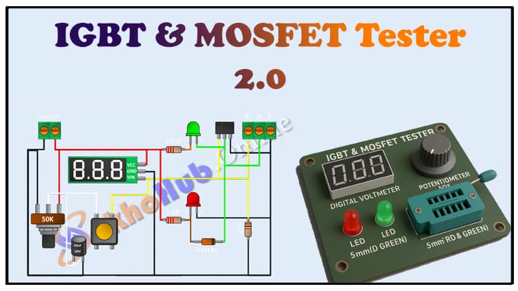
The circuit is designed to bias and test the gate, drain, and source of MOSFETs or the collector, emitter, and gate of IGBTs.
Power Supply: A simple 9V battery powers the entire tester.
Voltage Control: The 50K potentiometer provides adjustable gate voltage, simulating the ON/OFF control signal.
LEDs:
One LED indicates gate triggering.
The other LED lights up when current flows through the device under test.
Resistors: These limit current and provide the correct bias for the MOSFET/IGBT under test.
Voltmeter: Displays the output voltage, helping confirm the device’s switching behavior.
When you place the MOSFET/IGBT into the test socket (3-pin header/terminal block) and adjust the potentiometer, you can observe if the device switches correctly.
If the LEDs and voltmeter respond as expected → the component is good.
If there is no change or abnormal readings → the component is faulty.
Step-by-Step Building Guide
Gather Components
Collect all parts from the BOM table. Make sure your 9V battery is fresh.Prepare the Board
Use a perfboard to assemble the components. Place the 3-pin female header where the transistor/IGBT will be tested.Connect Resistors
Solder the 220 Ω resistor in series with the LED.
Use the 2.2 kΩ and 10 kΩ resistors for biasing the control circuit.
Install the Potentiometer
Connect the 50K potentiometer between the battery supply and the gate terminal of the device under test. This allows variable gate voltage control.Attach LEDs
Red LED for gate signal indication.
Green LED for load conduction indication.
Wire the Voltmeter
Connect the 9V voltmeter across the output terminals to observe switching voltage.Battery Connection
Use a 9V snap connector to power the tester.Testing a MOSFET/IGBT
Insert the device in the 3-pin female header.
Slowly adjust the potentiometer.
Observe LED behavior and voltmeter reading.
✅ Good Device → Turns ON/OFF smoothly with visible LED indication.
❌ Faulty Device → Stays always ON, always OFF, or produces abnormal readings.
Applications of IGBT & MOSFET Tester 2.0
Checking MOSFETs used in DC-DC converters
Testing IGBTs from inverters and UPS circuits
Repairing SMPS (Switch Mode Power Supplies)
Diagnosing amplifier circuits
Educational tool for electronics learners
FAQs
1. Can I test both N-channel and P-channel MOSFETs?
Yes, the tester can check both, but make sure you connect the terminals correctly.
2. Can this tester check high-voltage IGBTs?
Yes, but only their switching functionality. It doesn’t apply high voltage, so it won’t simulate full load conditions.
3. What if the LED lights up without gate control?
That usually indicates the device is shorted internally and is faulty.
4. Do I need a heatsink for testing?
No, the current here is minimal. No heating issues occur.
5. Is this better than using a multimeter?
Yes, because it applies real gate drive voltage instead of just diode-mode testing.
Conclusion
The IGBT & MOSFET Tester 2.0 is a must-have DIY electronics tool for hobbyists and professionals alike. It provides a quick, reliable, and low-cost method to check the health of MOSFETs and IGBTs without expensive test equipment.