

Simple IGBT Tester Circuit | Step-by-Step DIY Electronics Project
A simple IGBT tester circuit is an essential tool for electronics hobbyists and engineers. This simple IGBT tester circuit allows quick testing of IGBTs in power electronics projects. Using basic components, the simple IGBT tester circuit is easy to build and reliable. With this simple IGBT tester circuit, you can confirm if an IGBT is working. The simple IGBT tester circuit is low-cost. Building this simple IGBT tester circuit helps beginners. A simple IGBT tester circuit works with 5V supply. The simple IGBT tester circuit is explained with steps. This simple IGBT tester circuit is useful for students and hobbyists.
Introduction
In power electronics, IGBTs (Insulated Gate Bipolar Transistors) are widely used in motor drives, inverters, UPS systems, SMPS, and other high-power switching applications. Before using an IGBT in a circuit, it is always a good practice to test the device to ensure that it is working correctly.
A simple IGBT tester circuit provides a quick way to check if your IGBT is functional without using expensive equipment. By pressing a button, the IGBT gate is triggered, switching ON the device and lighting an LED as an indicator. When released, the IGBT turns OFF.
This article provides a complete step-by-step guide to designing and building your own simple IGBT tester circuit using common electronic components.
What is an IGBT?
The Insulated Gate Bipolar Transistor (IGBT) is a semiconductor device that combines the characteristics of a MOSFET (voltage control, fast switching) and a BJT (high current carrying capability).
MOSFET part → Controls the gate with very little input current.
BJT part → Provides high current gain and low saturation voltage.
This makes the IGBT ideal for:
Motor control
Inverter circuits
UPS systems
Induction heating
SMPS designs
For reference, you can read more about IGBTs on All About Circuits.
Circuit Diagram Explanation
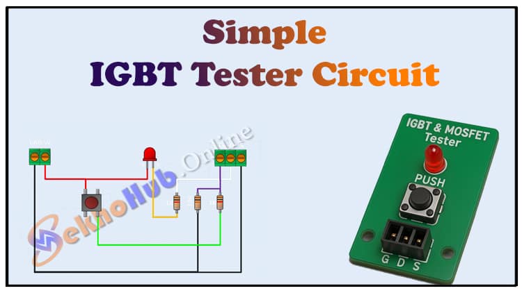
The circuit diagram of the simple IGBT tester circuit is straightforward.
Power Supply (5V DC): Provides biasing for the circuit.
Push Button: When pressed, it applies a gate voltage to the IGBT.
Resistors:
1kΩ resistors are used as gate current limiters.
10kΩ resistor works as a pull-down to discharge the gate when the button is released.
LED with 1kΩ resistor: Connected to indicate the ON/OFF status of the IGBT.
IGBT (Device Under Test): The main component being checked.
Working Principle:
When the push button is pressed, the IGBT gate receives a small positive voltage.
The IGBT switches ON, allowing current to flow through the LED, which glows.
When the button is released, the pull-down resistor discharges the gate, turning OFF the IGBT, and the LED goes off.
This ensures the IGBT is functional and can switch properly.
For more technical details on gate control, visit Electronics Tutorials.
Materials for the Project
| Component | Value/Type | Quantity | Buy Link |
|---|---|---|---|
| Power Supply | 5V DC | 1 | Buy Link |
| Push Button | SPST | 1 | Buy Link |
| LED | Red 5mm | 1 | Buy Link |
| Resistor | 1kΩ | 3 | Buy Link |
| Resistor | 10kΩ | 1 | Buy Link |
| IGBT | Any (e.g., IRG4PC50U, HGTG30N60A4D) | 1 | Buy Link |
| Terminal Blocks | 2-pin, 3-pin | 2 | Buy Link |
| Jumper Wires | Male-Female | As required | Buy Link |
Useful Tools
| Tool | Quantity | Purpose / Notes | Click & Buy |
|---|---|---|---|
| Soldering Iron Kit | 1 | For making permanent connections | Click & Buy |
| Solder Wire (60/40, 0.8mm) | 1 | Electrical soldering | Click & Buy |
| Wire Stripper & Cutter | 1 | Stripping jumper wires | Click & Buy |
| Mini Screwdriver Set | 1 | For module and relay terminal screws | Click & Buy |
| Multimeter | 1 | Testing voltages and continuity | Click & Buy |
| Hot Glue Gun (optional) | 1 | Securing components in place | Click & Buy |
| Small Pliers | 1 | Holding and bending wires | Click & Buy |
| Heat Shrink Tubing Set | 1 | Insulating exposed wires | Click & Buy |
Download Circuit Diagram

Step-by-Step Guide
Step 1: Gather Components
Collect all the components listed in the BOM. You can use a breadboard for testing or a PCB for permanent use.
Step 2: Connect the Power Supply
Provide a regulated 5V DC supply using a USB adapter, bench power supply, or battery with regulator.
Step 3: Wire the Push Button
Connect one side of the push button to +5V.
Connect the other side to the gate of the IGBT through a 1kΩ resistor.
Step 4: Add Pull-Down Resistor
Connect a 10kΩ resistor between the gate and ground. This ensures the IGBT gate is discharged when the button is released.
Step 5: Connect the LED
Connect the LED in series with a 1kΩ resistor from +5V to the collector (or drain).
The emitter (or source) should be connected to ground.
Step 6: Insert the IGBT
Place the IGBT in the circuit. Ensure proper pin orientation (Gate, Collector, Emitter).
Step 7: Test the Circuit
Power ON the circuit.
Press the push button. The LED should turn ON.
Release the button. The LED should turn OFF.
If the LED does not light, the IGBT may be faulty.
Applications of This Tester
Quick Testing of IGBTs: Before using in high-power circuits.
Educational Demonstrations: For students learning about power electronics.
DIY Projects: Hobbyists can verify devices before installation.
Troubleshooting: Identifying bad IGBTs in faulty circuits.
Advantages of This Circuit
Low cost
Simple design
Easy to build
Quick results
Portable
Limitations
Only checks switching function at low voltage (5V).
Cannot measure IGBT’s current rating or breakdown voltage.
For detailed testing, professional instruments are required.
FAQs
1. Can I use this circuit for MOSFETs as well?
Yes, this simple IGBT tester circuit can also be used to test MOSFETs since the gate operation is similar.
2. What if my LED does not glow?
Check wiring, power supply, and polarity. If correct, then the IGBT might be defective.
3. Can I use a 12V supply instead of 5V?
Yes, but make sure to increase the LED series resistor value to limit current.
4. Does this circuit test the IGBT under load conditions?
No, this circuit only checks the basic switching action, not high-current performance.
5. Which type of IGBT is supported?
Almost all low to medium power IGBTs can be tested. For very high-power modules, professional test equipment is needed.
For datasheets, check Texas Instruments or Infineon Technologies.
Safety Precautions
Always use low voltage supply for testing.
Do not test IGBTs directly in high-power circuits without verification.
Ensure correct pin orientation before powering the circuit.
For more safety guidelines, refer to OSHA Electrical Safety.
Conclusion
The simple IGBT tester circuit is a low-cost and effective way to quickly check the health of an IGBT device. By using just a handful of basic components such as resistors, a push button, and an LED, you can confirm whether an IGBT is functional.
This project is highly useful for electronics students, DIY hobbyists, and engineers working with power electronics. Although it cannot test the IGBT under full load, it is an excellent first step before placing the device in a larger circuit.
By following this guide, you can build your own simple IGBT tester circuit in just a few minutes and save both time and money when working with high-power semiconductor devices.