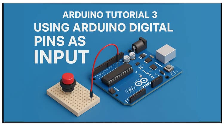
In this Arduino tutorial, you will learn how to use Arduino digital pins as input. The focus keyword Arduino digital pins as input is explained step by step. You will explore how Arduino digital pins as input work in real circuits, how to connect push buttons and LEDs, and how to write code. Using Arduino digital pins as input allows you to build interactive projects like switches, sensors, and automation systems.
This tutorial gives a complete explanation of Arduino digital pins as input, a BOM with buy links, a circuit diagram, and code. By the end, you will understand Arduino digital pins as input and how to use them in real projects. Arduino digital pins as input examples are tested live. Arduino digital pins as input is a core concept for beginners. Arduino digital pins as input help you expand projects with sensors and automation.
Introduction
Hi friends, welcome back to our Arduino tutorial series.
In the previous project (Tutorial 2), we learned how to use Arduino digital pins as OUTPUT, where we controlled an LED. That was our first step in making Arduino control external components.
Now in Tutorial 3, we will learn how to use Arduino digital pins as INPUT. This means we’ll connect devices like push buttons, switches, and sensors to Arduino, and Arduino will read their states (pressed/released, HIGH/LOW, ON/OFF).
We’ll build a simple push button LED project first, then extend it to a blinking effect. Along the way, we’ll:
Explain the components required
Show the circuit diagram and how it works
Provide Arduino code examples
Discuss how digitalRead() works
Answer common beginner questions
So let’s begin!
Materials for the Project
Here’s the list of components you’ll need for this tutorial.
| S.No | Component | Quantity | Description | Buy Link |
|---|---|---|---|---|
| 1 | Arduino Uno | 1 | Main microcontroller board | Buy |
| 2 | Push Button | 1 | Standard 4-pin push button | Buy |
| 3 | LED (Red) | 1 | 5mm LED for output | Buy |
| 4 | Resistor 10kΩ | 1 | Pull-down resistor | Buy |
| 5 | Resistor 100Ω | 1 | Current limiting resistor for LED | Buy |
| 6 | Breadboard | 1 | For circuit building | Buy |
| 7 | Jumper Wires | Several | Male-to-male wires | Buy |
| 8 | USB Cable | 1 | Arduino to PC connection | Buy |
Circuit Diagram Explanation
The wiring is very simple:
Push Button Connection
One pin of the button → +5V
The opposite pin of the button → Arduino D2
A 10kΩ resistor connects D2 to GND (pull-down resistor).
➝ This ensures D2 reads LOW when the button is not pressed, and HIGH when pressed.
LED Connection
LED anode (+) → Arduino D3
LED cathode (-) → 100Ω resistor → GND
➝ This protects the LED from excess current.
So the logic is:
Button → Input at D2
LED → Output at D3
Step-by-Step Guide
Step 1: Connect the Circuit
As per the explanation above, assemble the push button and LED circuit on a breadboard.
Step 2: Upload First Code
Here’s the first simple code:
Step 3: How It Works
pinMode(buttonPin, INPUT); → tells Arduino to listen to pin D2.
pinMode(ledPin, OUTPUT); → tells Arduino to control pin D3.
digitalRead(buttonPin); → reads if the button is pressed (HIGH) or not (LOW).
digitalWrite(ledPin, … ); → sends that state to the LED.
Result:
Press button → LED ON
Release button → LED OFF
Making It More Interesting
Now let’s modify the code to make the LED blink while the button is pressed.
Working
Button pressed → LED blinks ON/OFF every second.
Button released → LED stays OFF.
Understanding Pull-Down Resistor
Why did we connect a 10k resistor to ground?
Without it, pin D2 would float when the button is not pressed, giving random values.
Pull-down resistor ensures a stable LOW when button is not pressed.
Practical Applications
Using Arduino digital pins as input is not limited to push buttons. You can connect:
Switches → Turn appliances ON/OFF.
Sensors (PIR, IR, LDR, etc.) → Detect motion, obstacles, or light.
Keypads → For entering numbers or passwords.
Limit switches → For robotics and CNC machines.
FAQs
Q1: Can I use Arduino digital pins as both input and output?
Yes, you can change pinMode dynamically during runtime, but usually pins are fixed for stability.
Q2: What is the maximum input voltage for Arduino digital pins?
For Arduino Uno (ATmega328p), input voltage must be between 0V and 5V. Higher voltage can damage the pin.
Q3: Do I always need a pull-down resistor?
If you use pinMode(pin, INPUT), yes. But if you use pinMode(pin, INPUT_PULLUP), Arduino uses its internal 20–50kΩ pull-up resistor.
Q4: Why does my LED glow dimly even when the button is not pressed?
That happens if the input pin is floating. Always use a resistor or enable INPUT_PULLUP.
Q5: Can I connect sensors directly instead of a button?
Yes. Many sensors provide digital HIGH/LOW output that can be read using digitalRead().
Conclusion
In this tutorial, we learned how to use Arduino digital pins as INPUT.
We:
Built a push button circuit
Used a 10k pull-down resistor for stable readings
Wrote simple Arduino code using
digitalRead()Modified the code to make the LED blink when pressed
Discussed real-world uses and FAQs
This forms the foundation of interactive Arduino projects. From here, you can connect more advanced digital sensors, switches, and control devices to make your projects smarter.
Stay tuned for Arduino Tutorial 4, where we’ll move into another exciting feature of Arduino.


