
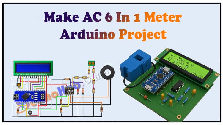
In this guide, we will learn how to make an AC 6 in 1 Meter using Arduino. The AC 6 in 1 Meter project allows you to measure AC voltage, AC current, frequency, power, energy, and temperature in real time. With Arduino at its core, the AC 6 in 1 Meter is ideal for DIY electronics enthusiasts, students, and engineers who want to build a compact monitoring tool.
The AC 6 in 1 Meter uses LM358 IC, CT sensor, resistors, and an LCD for displaying measurements. This step-by-step tutorial explains the complete circuit, components, and connections required for the AC 6 in 1 Meter. If you are looking for a practical Arduino project, the AC 6 in 1 Meter is a great choice. Build your own AC 6 in 1 Meter and monitor electrical parameters efficiently.
Introduction
Hi friends, in this project I’m going to show you how to make an AC 6 in 1 Meter.
This DIY Arduino-based project can measure:
AC Voltage
AC Current
AC Frequency
Power (W)
Energy (kWh)
Temperature
It’s a compact yet powerful monitoring tool for electrical loads, household appliances, and experimental setups. Let’s get started.

Materials for the Project
| S.No | Component | Quantity | Buy Link |
|---|---|---|---|
| 1 | Arduino Nano | 1 | Buy Link |
| 2 | LM358 IC (Op-Amp) | 1 | Buy LM358 |
| 3 | CT Sensor (Current Transformer) | 1 | Buy CT Sensor |
| 4 | 16×2 LCD Display | 1 | Buy 16×2 LCD |
| 5 | 10K Resistors | 4 | Buy Resistors Kit |
| 6 | 4.7k Resistor | 1 | — |
| 7 | 2.2k Resistor | 1 | — |
| 8 | 47Ω Resistor | 1 | — |
| 9 | 470k Resistors | 6 | — |
| 10 | 10K Trim Pot | 1 | Buy Trim Pot |
| 11 | 10K Thermistor (NTC) | 1 | Buy Thermistor |
| 12 | Two-Pin Terminal Block | 1 | — |
| 13 | Jumper Wires & Breadboard / PCB | — | Buy Jumper Wires |
| 14 | Power Supply 5V (USB or Adapter) | 1 | Buy Adapter |
Useful Tools
| Tool | Quantity | Purpose / Notes | Click & Buy |
|---|---|---|---|
| Soldering Iron Kit | 1 | For making permanent connections | Click & Buy |
| Solder Wire (60/40, 0.8mm) | 1 | Electrical soldering | Click & Buy |
| Wire Stripper & Cutter | 1 | Stripping jumper wires | Click & Buy |
| Mini Screwdriver Set | 1 | For module and relay terminal screws | Click & Buy |
| Multimeter | 1 | Testing voltages and continuity | Click & Buy |
| Hot Glue Gun (optional) | 1 | Securing components in place | Click & Buy |
| Small Pliers | 1 | Holding and bending wires | Click & Buy |
| Heat Shrink Tubing Set | 1 | Insulating exposed wires | Click & Buy |
Circuit Diagram
The circuit mainly involves:
LM358 IC for signal conditioning of current and voltage inputs.
Resistor voltage divider network for AC voltage sensing.
CT sensor for current measurement.
Thermistor for temperature.
Arduino for processing signals.
LCD 16×2 for displaying results.

Step-by-Step Connections
Step 1: Arduino Setup
First I’m going to connect Arduino.
Step 2: LM358 IC Wiring
Then I’m going to connect lm358 IC and connect its pin number 8 to 5 pin of arbino.
it’s pin number 4 to ground.
it’s spin number 7 to A1 pin of arbino.
it’s pin number 1 to A0 pin of arbino .
Step 3: Resistors with LM358
Then I’m going to connect a 10K resistor and connect its one pin to pin number one of the IC and its other pin to pin number two of the IC.
Then I’m going to connect another 10K resistor and connect its one pin to pin number two of the IC and its other pin to ground .
Then I’m going to connect a 47 Ohm resistor and connect its one pin to pin number three of the IC and its other pin to ground.
Then I’m going to connect the current Transformer and connect its one pin to pin number three of the IC and its other pin to ground.
Then I’m going to connect a 10K resistor and connect its one pin to pin number seven of the IC and its other pin to pin number six of the IC.
Then I’m going to connect a 4.7k resistor and connect its one pin to pin number six of the IC and its other pin to ground.
Then I’m going to connect a 2.2k resistor and connect its one pin to pin number five of the IC and its other pin to ground.
Step 4: Voltage Divider with 470k Resistors
- Then I’m going to connect a two- pin terminal block then I’m going to connect a 470k resistor and connect its one pin to pin number five of the IC.
- Then I’m going to connect another 470k resistor and connect its one pin to remaining pin of the previous 470k resistor.
Step 5: Two-Pin Terminal Block
- Then I’m going to connect another 470k resistor and connect its one pin to previous 470K resistor and its other pin to one pin off the two pin terminal block.
- Then I’m going to connect a 470k resistor and connect its one pin to ground.
- Then I’m going to connect another 470k resistor and connect its one pin to remaining pin off the previous 470k resistor.
- Then I’m going to connect a 470k resistor and connect its one pin to remaining pin off the previous 470k resistor and its other pin to remaining pin of the two- pin terminal block.
Step 6: LCD Display Wiring
- Then I’m going to connect the LCD display and connect its spin number 1 5 7 8 9 10 and 16 to ground .
- it’s pin number two and 15 to five pin of arbino.
- it’s pin number four to D7 pin of Arduino .
- it’s pin number six to D6 pin of Arduino .
- it’s pin number 11 to D5 pin of Arduino.
- it’s pin number 12 to D4 pin of arino.
- it’s pin number 13 to D3 pin of arino.
- it’s pin number 14 to D2 pin of Arduino.
Step 7: Trim Pot
- Then I’m going to connect a 10K trim pod and connect its one side pin to five pin of arbino it center pin to pin number three of the LCD and its other side pin to ground.
Step 8: Temperature Sensor
- Then connect a 10K Thermistor and connect its one pin to A2 pin of arino and its other pin to five pin off adino.
- then connect a 10K resistor and connect it it’s one pin to A2 pin of arino and its other pin to ground.
- so we have completed all the connections now let’s upload the code to adino and test the project.
Working Principle
Voltage Measurement: The resistor divider reduces AC mains voltage to a safe level. Arduino reads this via LM358.
Current Measurement: CT sensor produces a proportional AC signal. LM358 amplifies it for Arduino.
Frequency: Arduino measures zero-crossing points of the AC waveform.
Power & Energy: Calculated using V × I × PF over time.
Temperature: Thermistor changes resistance with heat; Arduino converts it into °C.
LCD Output: Displays all six values in real-time.
Uploading the Code
Connect Arduino to your PC.
Open Arduino IDE.
Paste the code (to be added).
Select the correct board and COM port.
Upload the code and watch values on the LCD.
Arduino Code
Applications
Household appliance monitoring
DIY energy meters
Laboratory experiments
Power quality monitoring
FAQs
Q1: What is the accuracy of the AC 6 in 1 Meter?
Accuracy depends on resistor tolerance, CT sensor quality, and calibration. With proper calibration, ±2% accuracy is achievable.
Q2: Can this project measure DC parameters?
No, this project is designed for AC only. For DC, a shunt resistor method is used.
Q3: How do I calibrate voltage and current?
Compare readings with a commercial multimeter and adjust scaling factors in the Arduino code.
Q4: Can I use an OLED instead of LCD?
Yes, but you’ll need to change the code to match the OLED library.
Q5: Is this project safe for beginners?
Since it involves AC mains, proper insulation and caution are required. Beginners should seek supervision.