
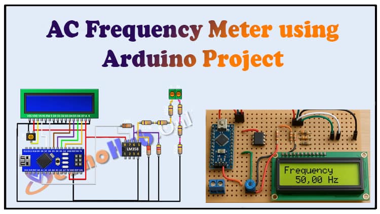
In this guide, we explore how to build an AC Frequency Meter using Arduino for measuring AC signal frequency accurately. This AC Frequency Meter using Arduino works with LM358 IC, resistors, and an LCD display. By following step-by-step instructions, you’ll learn the design, circuit diagram, and coding of an AC Frequency Meter using Arduino. The AC Frequency Meter using Arduino provides real-time readings, making it ideal for DIY electronics.
Beginners and hobbyists can benefit from this AC Frequency Meter using Arduino tutorial. Components are affordable, and connections are simple. With an AC Frequency Meter using Arduino, measuring high-voltage frequency signals becomes easy. Whether you’re testing circuits, doing electrical experiments, or working on power electronics, this AC Frequency Meter using Arduino project offers accuracy and efficiency. Build your own AC Frequency Meter using Arduino today with this detailed explanation.
Introduction
Measuring the frequency of AC signals is a common requirement in electronics and electrical engineering projects. Whether you are testing an inverter, analyzing generator output, or studying power electronics, having an AC Frequency Meter using Arduino makes the task much easier.
In this article, we’ll design and build a reliable and cost-effective AC frequency measurement system with Arduino. The project uses an LM358 IC for signal conditioning, a few resistors for scaling, and a 16×2 LCD display to show the measured frequency.
By the end of this guide, you’ll have a working AC Frequency Meter using Arduino, along with the knowledge to modify and improve it for your applications.
Why Build an AC Frequency Meter?
Power systems testing – measure mains frequency (50Hz/60Hz).
Generator monitoring – track output frequency stability.
Inverter testing – check if inverter frequency is within the desired range.
Educational purposes – learn about signal processing and Arduino applications.
DIY electronics labs – low-cost alternative to commercial frequency counters.
Working Principle of the Project
The working of this AC Frequency Meter using Arduino is straightforward:
The AC signal is first stepped down using a resistor divider network.
The LM358 IC converts the signal into a form readable by Arduino.
Arduino measures the time between signal cycles using interrupt functions.
The calculated frequency is displayed on the 16×2 LCD screen.
This method ensures accurate and safe measurement of AC signal frequency without exposing the Arduino directly to high voltage.
Materials for the Project
| Component | Specification | Quantity | Buy Link |
|---|---|---|---|
| Arduino NANO | ATmega328P | 1 | Buy Here |
| LM358 IC | Dual Op-Amp | 1 | Buy Here |
| Resistor | 10kΩ | 1 | Buy Here |
| Resistor | 4.7kΩ | 1 | Buy Here |
| Resistor | 2.2kΩ | 1 | Buy Here |
| Resistors | 470kΩ | 6 | Buy Here |
| 16×2 LCD | Alphanumeric | 1 | Buy Here |
| Potentiometer | 10kΩ Trimpot | 1 | Buy Here |
| Terminal Block | 2-pin | 1 | Buy Here |
| Breadboard/Wires | Jumper wires | As needed | Buy Here |
| Power Supply | 5V regulated | 1 | Buy Here |
Useful Tools
| Tool | Quantity | Purpose / Notes | Click & Buy |
|---|---|---|---|
| Soldering Iron Kit | 1 | For making permanent connections | Click & Buy |
| Solder Wire (60/40, 0.8mm) | 1 | Electrical soldering | Click & Buy |
| Wire Stripper & Cutter | 1 | Stripping jumper wires | Click & Buy |
| Mini Screwdriver Set | 1 | For module and relay terminal screws | Click & Buy |
| Multimeter | 1 | Testing voltages and continuity | Click & Buy |
| Hot Glue Gun (optional) | 1 | Securing components in place | Click & Buy |
| Small Pliers | 1 | Holding and bending wires | Click & Buy |
| Heat Shrink Tubing Set | 1 | Insulating exposed wires | Click & Buy |
Circuit Diagram Explanation
Signal Input Network
The AC signal is fed through a chain of 470kΩ resistors forming a high-value voltage divider.
This ensures the input voltage is stepped down safely to a level that the LM358 IC can process.
Signal Conditioning (LM358 IC)
The LM358 is configured as a comparator.
Resistors (10k, 4.7k, and 2.2k) set reference levels.
The output is a square wave signal proportional to the AC input.
Arduino and LCD Interface
The Arduino reads the signal at its A1 pin.
It processes the frequency using code logic.
The measured frequency is displayed on the 16×2 LCD connected to Arduino’s digital pins.
Download Circuit Diagram

Step-by-Step Build Guide
Step 1: Setting up Arduino and LM358
Connect pin 8 of LM358 → Arduino 5V.
Connect pin 4 of LM358 → GND.
Connect pin 7 of LM358 → Arduino A1.
Step 2: Adding Resistors for Signal Conditioning
Place a 10kΩ resistor between pins 7 and 6 of LM358.
Place a 4.7kΩ resistor from pin 6 to GND.
Place a 2.2kΩ resistor from pin 5 to GND.
Step 3: Voltage Divider with 470kΩ Resistors
Chain multiple 470kΩ resistors in series to reduce AC input voltage.
Connect one side to the terminal block (for AC signal input).
Connect the other ends appropriately to pin 5 of LM358 and ground.
Step 4: Connecting the LCD Display
LCD pins 1, 5, 7, 8, 9, 10, 16 → GND.
LCD pins 2 & 15 → Arduino 5V.
LCD pin 4 → Arduino D7.
LCD pin 6 → Arduino D6.
LCD pin 11 → Arduino D5.
LCD pin 12 → Arduino D4.
LCD pin 13 → Arduino D3.
LCD pin 14 → Arduino D2.
Step 5: Adding the Contrast Control
Connect 10kΩ trimpot:
One side → 5V.
Other side → GND.
Center → LCD pin 3.
Step 6: Uploading the Code
Arduino Code
Write or upload Arduino code to measure frequency using interrupts.
The code will calculate the time interval between signal edges and convert it to frequency.
Step 7: Testing the Project
Provide a safe AC input signal to the terminal block.
Power on the system.
Observe the frequency displayed on the LCD.
Applications of AC Frequency Meter using Arduino
Testing AC mains frequency stability (50Hz or 60Hz).
Measuring generator frequency during load variations.
Debugging inverter circuits for correct frequency output.
Educational demonstration in electronics labs.
DIY power electronics experiments.
Safety Precautions
Always use a step-down isolation transformer when dealing with mains AC.
Never connect high voltage AC directly to Arduino.
Double-check resistor connections before applying input.
Use insulated probes and avoid touching the circuit while powered.
FAQs
1. Can this project measure both 50Hz and 60Hz signals?
Yes, the AC Frequency Meter using Arduino can measure both, as the Arduino code is designed to calculate any frequency in a suitable range.
2. What is the maximum frequency this project can measure?
It depends on Arduino’s timer and code implementation, but typically it can measure up to a few kHz accurately.
3. Do I need to use an isolation transformer?
Yes, for safety reasons you should always use an isolation transformer when connecting mains AC to your project.
4. Can I use an OLED display instead of LCD?
Yes, you can replace the LCD with an I2C OLED display by modifying the code accordingly.
5. How accurate is this frequency meter?
The accuracy mainly depends on Arduino’s clock and code precision. For power applications (50Hz/60Hz), it is sufficiently accurate.
Conclusion
Building an AC Frequency Meter using Arduino is an excellent project for students, hobbyists, and engineers who want to measure AC signal frequency without expensive lab equipment. By combining the LM358 IC, resistors, Arduino, and an LCD, you can create a simple yet effective frequency meter.
This project provides practical learning about signal conditioning, voltage dividers, and Arduino programming, while also offering a functional tool for testing electrical systems.