 What is CD4510 IC | How CD4510 IC Works: Pinout, Circuit, and Applications
 What is CD4510 IC | How CD4510 IC Works: Pinout, Circuit, and Applications
The CD4510 IC is a versatile presettable BCD up-down counter used in digital electronics. This guide explains the CD4510 IC in detail, covering its pin configuration, working principle, and practical hardware circuits. Learn how the CD4510 IC counts up and down, how to use its preset feature, and explore step-by-step hardware implementations. We also include a detailed BOM table and circuit explanations. By the end, you will understand the CD4510 IC thoroughly, including how to connect it in up counter, down counter, and preset counter circuits. This guide focuses on theoretical understanding and hardware implementation of the CD4510 IC, making it ideal for electronics enthusiasts and students looking to explore digital counters.
Introduction
Digital counters are foundational components in electronics, enabling counting, timing, and sequencing operations. Among these, the CD4510 IC is a popular choice for BCD (Binary-Coded Decimal) counting. Unlike ordinary counters, it is presettable, meaning you can start counting from a specific value instead of zero. The CD4510 IC is designed to count both upwards and downwards, making it highly versatile in applications like digital clocks, frequency counters, and event counters. In this article, we provide a comprehensive explanation of the CD4510 IC, its pin configuration, working principles, and hardware circuit implementations.
What is CD4510 IC?
The CD4510 IC is a presettable BCD up-down counter. Here’s what that means:
Up-Down Counter: Can count numbers in ascending or descending order based on a control signal.
BCD (Binary Coded Decimal): Counts from 0 to 9 in binary format.
Presettable Feature: Allows loading a specific starting value instead of starting from zero.
The CD4510 IC is commonly used in digital electronics projects where precise counting and control are required. Its ability to cascade with other counters makes it suitable for higher-digit counting applications.
Pin Configuration of CD4510 IC
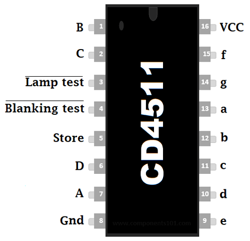
Understanding the pin configuration is crucial for hardware implementation. The CD4510 IC comes in a 16-pin DIP package with the following pins:
| Pin Number | Function | Description | |
|---|---|---|---|
| 1 | Preset Enable (PE) | Activates presetting of input data | |
| 2 | QD Output | Most significant output bit | |
| 3 | Input B | Preset input | |
| 4 | Input A | Preset input | |
| 5 | Carry In (CI) | For cascading counters | |
| 6 | QC Output | Output bit | |
| 7 | Carry Out (CO) | Outputs carry for cascading | |
| 8 | GND | Ground | |
| 9 | Reset | Resets counter to 0 | |
| 10 | Up/Down | HIGH = Up, LOW = Down | |
| 11 | QB Output | Output bit | |
| 12 | Input D | Preset input | |
| 13 | Input C | Preset input | |
| 14 | QA Output | Least significant output bit | |
| 15 | Clock | Clock input | |
| 16 | VCC | Positive power supply |
Useful Tools
| Tool | Quantity | Purpose / Notes | Click & Buy |
|---|---|---|---|
| Soldering Iron Kit | 1 | For making permanent connections | Click & Buy |
| Solder Wire (60/40, 0.8mm) | 1 | Electrical soldering | Click & Buy |
| Wire Stripper & Cutter | 1 | Stripping jumper wires | Click & Buy |
| Mini Screwdriver Set | 1 | For module and relay terminal screws | Click & Buy |
| Multimeter | 1 | Testing voltages and continuity | Click & Buy |
| Hot Glue Gun (optional) | 1 | Securing components in place | Click & Buy |
| Small Pliers | 1 | Holding and bending wires | Click & Buy |
| Heat Shrink Tubing Set | 1 | Insulating exposed wires | Click & Buy |
Truth Table and Working Principle
The CD4510 IC counts in BCD format, from 0 to 9. The Up/Down pin determines the counting direction:
Up/Down = HIGH → Counter increments (0 → 1 → … → 9)
Up/Down = LOW → Counter decrements (9 → 8 → … → 0)
Reset pin: Forces the counter to zero immediately.
Preset pins: When Preset Enable is HIGH, the binary value applied to input pins A-D is loaded into the counter.
BCD Output (QA-QD): Four output bits represent the decimal number in binary.
| Up/Down | Clock Pulse | Output QA-QD | Description |
|---|---|---|---|
| HIGH | 1 | 0000 → 0001 | Counting Up |
| LOW | 1 | 1001 → 1000 | Counting Down |
| X | 0 | 0000 | No change |
Materials for the Project
| Component | Quantity | Description | Buy Link |
|---|---|---|---|
| CD4510 IC | 1 | Presettable BCD Up-Down Counter | Buy Link |
| 7404 IC | 1 | Hex Inverter for clock shaping | Buy Link |
| 10kΩ Resistor | 4 | Pull-up resistors | Buy Link |
| 0.1µF Capacitor | 2 | Debouncing / clock stability | Buy Link |
| Push Button | 1 | Manual clock input | Buy Link |
| LED | 4 | Display outputs | Buy Link |
| 220Ω Resistor | 4 | Current limiting for LEDs | Buy Link |
| Breadboard & Wires | 1 | Hardware connections | Buy Link |
Circuit Diagrams and Hardware Implementation
1. Up Counter Circuit
Connect VCC to 5V and GND to ground.
Connect Up/Down pin to HIGH.
Connect Clock pin to a push-button or clock pulse generator.
Outputs QA-QD connected to LEDs via 220Ω resistors.
Observe LEDs increment from 0 to 9 with each clock pulse.
2. Down Counter Circuit
Keep Up/Down pin LOW.
Connect clock and output LEDs as before.
LEDs now decrement from 9 to 0 with each clock pulse.
3. Preset Counter Circuit
Set Preset Enable pin HIGH.
Apply a binary value (A-D inputs) for the starting number.
Clock pulses continue counting up or down from the preset value.
Note: Debouncing capacitor (0.1µF) improves stability when using push-button as clock.
Step-by-Step Hardware Guide
Place CD4510 IC on a breadboard.
Connect Pin 16 → VCC, Pin 8 → GND.
Connect Up/Down pin according to desired count direction.
Connect QA-QD outputs to LEDs through 220Ω resistors.
Connect clock input to push-button or signal generator.
If using preset feature, connect inputs A-D and Preset Enable pin.
Connect reset pin through a push-button for manual reset.
Apply power; observe counting behavior as per circuit type.
Applications of CD4510 IC
Digital clocks and timers
Frequency counters
Event counters in industrial automation
Scoreboards
Sequential logic circuits
Educational electronics projects
FAQs
1. What is the main function of CD4510 IC?
The CD4510 IC is a presettable BCD up-down counter used for counting, timing, and sequencing operations.
2. Can CD4510 IC count beyond 9?
No, it counts only in BCD (0–9). For higher ranges, multiple ICs can be cascaded.
3. How does the preset feature work?
When the Preset Enable pin is HIGH, binary values applied to input pins A-D are loaded into the counter.
4. What voltage is required for CD4510 IC?
Typically, 3–15V DC, commonly 5V for digital circuits.
5. Can I use it with LEDs?
Yes, outputs QA-QD can drive LEDs via current-limiting resistors.
Conclusion
The CD4510 IC is a powerful and versatile BCD up-down counter suitable for a wide range of digital electronics applications. Its ability to count up, count down, and load preset values makes it ideal for learning digital logic and implementing practical counting circuits. By understanding its pin configuration, working principle, and hardware implementation, electronics enthusiasts can easily integrate the CD4510 IC into various projects, from simple counters to more complex sequential logic systems.