
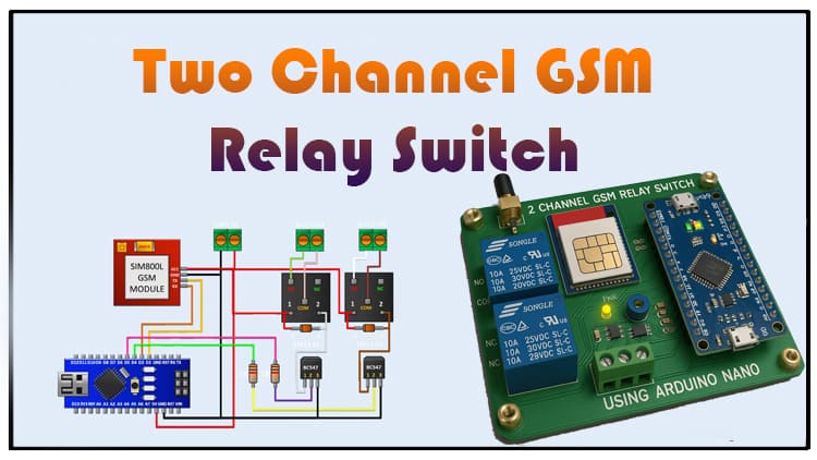
This article explains how to build a two channel GSM relay switch using Arduino. The two channel GSM relay switch allows remote control of electrical devices via SMS. Learn about the components, circuit design, and working principle of the two channel GSM relay switch in detail. The two channel GSM relay switch is an ideal DIY project for beginners and advanced electronics hobbyists.
Introduction
Remote switching has become a vital part of modern electronics. Instead of being physically present to turn on or off devices, you can control them using wireless communication. One of the simplest yet effective ways to achieve this is by using GSM technology.
In this project, we are going to build a two channel GSM relay switch using Arduino. By sending an SMS command from your mobile phone, you can control two different electrical loads such as lights, fans, pumps, or appliances.
This project is highly practical for home automation, industrial automation, and IoT applications where remote access is needed.

Materials for the Project
| Component | Quantity | Description | Buy Link |
|---|---|---|---|
| Arduino Nano | 1 | Microcontroller board | Buy Here |
| GSM Module (SIM800L/SIM900A) | 1 | For SMS communication | Buy Here |
| BC547 Transistor | 2 | NPN transistor for relay driver | Buy Here |
| 5V Relay Module | 2 | For switching AC/DC loads | Buy Here |
| 1K Resistor | 2 | Base resistor for transistor | Buy Here |
| 1N4148 Diode | 2 | Flyback diode for relay protection | Buy Here |
| 2-Pin Terminal Block | 2 | Load connection | Buy Here |
| Jumper Wires | As required | For circuit connections | Buy Here |
| Power Supply (5V 2A) | 1 | To power Arduino + GSM module | Buy Here |
Useful Tools
| Tool | Quantity | Purpose / Notes | Click & Buy |
|---|---|---|---|
| Soldering Iron Kit | 1 | For making permanent connections | Click & Buy |
| Solder Wire (60/40, 0.8mm) | 1 | Electrical soldering | Click & Buy |
| Wire Stripper & Cutter | 1 | Stripping jumper wires | Click & Buy |
| Mini Screwdriver Set | 1 | For module and relay terminal screws | Click & Buy |
| Multimeter | 1 | Testing voltages and continuity | Click & Buy |
| Hot Glue Gun (optional) | 1 | Securing components in place | Click & Buy |
| Small Pliers | 1 | Holding and bending wires | Click & Buy |
| Heat Shrink Tubing Set | 1 | Insulating exposed wires | Click & Buy |
Circuit Diagram Explanation
The circuit is built around Arduino Nano, a GSM module, and two relays controlled by transistors.
Power Section
Arduino provides a regulated 5V supply to both the GSM module and relays.
A 2-pin terminal block is used to connect external DC power.
GSM Module Connections
VCC → Arduino 5V
GND → Arduino GND
TX → D2 pin of Arduino
RX → D3 pin of Arduino
This setup allows Arduino to send and receive AT commands from the GSM module.
Relay Driver Circuit
Each relay is driven by a BC547 transistor.
The base of the transistor is connected to Arduino pins (D4 and D5) through a 1K resistor.
The collector drives the relay coil, and the emitter is connected to ground.
Flyback Diode Protection
A 1N4148 diode is placed across each relay coil to protect the transistor from voltage spikes when the relay switches.
Relay Output
Each relay is connected to a 2-pin terminal block for easy connection to AC or DC loads.
Devices like lights, fans, or pumps can be controlled.
Download Circuit Diagram

Working Principle
The two channel GSM relay switch works as follows:
When you send an SMS (e.g., “ON1” or “OFF1”), the GSM module receives the message.
Arduino reads the incoming SMS via the serial communication pins (D2 and D3).
Based on the message, Arduino activates or deactivates the corresponding relay by sending a HIGH or LOW signal to the transistor base.
The transistor switches the relay coil ON or OFF, which in turn controls the connected electrical load.
This way, two separate devices can be controlled remotely via SMS.
Step-by-Step Guide
Step 1: Preparing the Components
Gather all the required components listed in the BOM. Make sure you have a working SIM card (preferably 2G supported) for the GSM module.
Step 2: Wiring the Arduino and GSM Module
Connect VCC of GSM to Arduino 5V.
Connect GND of GSM to Arduino GND.
Connect TX of GSM → D2 of Arduino.
Connect RX of GSM → D3 of Arduino.
Step 3: Relay Driver Circuit
Connect BC547 transistor pin 3 (emitter) to ground.
Connect pin 2 (base) to Arduino pin D4 via a 1K resistor.
Connect pin 1 (collector) to one coil terminal of the relay.
Connect the other relay coil terminal to Arduino 5V.
Place a diode (1N4148) across the relay coil for protection.
Repeat the same steps for the second relay, using Arduino pin D5.
Step 4: Load Connection
Connect the common terminal of each relay to the AC live wire.
Connect the normally open terminal to the device (lamp, fan, pump).
Neutral wire goes directly to the device.
⚠️ Safety Note: Be cautious while handling AC mains connections. Use proper insulation and enclosures.
Step 5: Uploading Arduino Code
Write an Arduino sketch to read SMS from the GSM module.
Use simple AT commands to read incoming messages.
If the SMS contains “ON1”, turn on Relay 1. If it contains “OFF1”, turn off Relay 1.
Similarly, use “ON2” and “OFF2” for Relay 2.
Step 6: Testing the Project
Insert the SIM card into the GSM module.
Power up the circuit.
Send an SMS from your mobile with the command “ON1”. The first relay should activate.
Send “OFF1” and the relay will turn off.
Repeat the same for the second relay with “ON2” and “OFF2”.
Congratulations! Your two channel GSM relay switch is ready to use.
Applications
Home Automation – Control lights, fans, or other appliances via SMS.
Industrial Automation – Switch machines remotely.
Agriculture – Control water pumps from distant locations.
Security Systems – Turn ON/OFF alarms or CCTV systems.
IoT Projects – Extend this to internet-controlled devices.
Advantages
Simple and cost-effective.
Works with any mobile network supporting GSM.
Can be scaled up to multiple channels.
No internet required – works in remote areas.
Limitations
Requires a GSM network (not suitable where signals are weak).
Switching delay due to SMS processing time.
Limited to the number of relays Arduino can handle.
FAQs
Q1. Can I use this project with 220V AC appliances?
Yes, but make sure to use a 5V relay with proper current rating. Ensure electrical safety and isolation.
Q2. Can I expand it to more than 2 channels?
Yes, you can add more relays by using additional Arduino pins and transistors.
Q3. Which SIM card should I use?
A standard 2G GSM SIM card is recommended. Some 3G/4G SIMs also work if they support GSM fallback.
Q4. Can I use Arduino Nano instead of Nano?
Yes, Arduino Nano works perfectly with the same wiring.
Q5. Can this be controlled with internet (IoT)?
This version works with SMS. For IoT control, you can use ESP32 or NodeMCU with Wi-Fi.
Conclusion
We successfully built a two channel GSM relay switch using Arduino. This project demonstrates how easily we can integrate GSM communication with microcontrollers to remotely control appliances. It’s a powerful yet simple project suitable for DIY enthusiasts, students, and engineers.
You can extend this project by adding more relays, sensors, or even integrating with IoT platforms for enhanced automation.