

A Servo Motor Tester is a simple circuit that allows users to test and control servo motors easily. This Servo Motor Tester is built using a 555 Timer IC, resistors, a capacitor, and two push buttons on a perf board. The Servo Motor Tester can generate precise PWM signals to rotate the servo motor clockwise, anticlockwise, or hold it at a specific position.
Using this Servo Motor Tester, you can check servo performance before connecting it to microcontrollers like Arduino or ESP32. This Servo Motor Tester is ideal for robotics, RC vehicles, and automation projects. Learn how to make your own Servo Motor Tester with a 555 Timer IC by following the step-by-step build guide, circuit diagram explanation, and components list provided. Build your own Servo Motor Tester today and explore servo control practically.
Introduction
Servo motors are an essential part of robotics, automation, and control systems. Whether you’re designing a robotic arm, a drone gimbal, or an RC car steering system you’ll need a reliable way to test servo motors before integrating them into your project.
In this tutorial, we’ll learn how to make a Servo Motor Tester using a 555 Timer IC. The 555 is one of the most versatile ICs in electronics capable of generating precise timing and PWM signals. By combining it with a few resistors, a capacitor, and push buttons, we can create a simple yet powerful circuit that can control any standard servo motor without the need for a microcontroller.
This project is perfect for beginners, hobbyists, and professionals who want a quick way to test servos directly.
Materials for the Project
| No. | Component Name | Quantity | Description | Buy Link |
|---|---|---|---|---|
| 1 | 555 Timer IC | 1 | Main PWM generator IC | Buy Link |
| 2 | LED | 1 | Output indicator | Buy Link |
| 3 | Push Button | 2 | For manual PWM control (CW/CCW) | Buy Link |
| 4 | Capacitor 0.1µF (104) | 1 | Timing capacitor | Buy Link |
| 5 | Resistor 1kΩ | 1 | Current limiter for LED/output | Buy Link |
| 6 | Resistor 10kΩ | 1 | Reset pull-up resistor | Buy Link |
| 7 | Resistor 100kΩ | 1 | Timing resistor | Buy Link |
| 8 | Resistor 220kΩ | 1 | PWM control resistor | Buy Link |
| 9 | 3-Pin Male Header | 1 | Servo signal output pins | Buy Link |
| 10 | 2-Pin Terminal Block | 1 | Power input connector | Buy Link |
| 11 | Perf Board | 1 | Circuit assembly board | Buy Link |
| 12 | Jumper Wires | As required | Connections | Buy Link |
Pin Connections of 555 Timer.
| Pin | Name | Connection |
|---|---|---|
| 1 | GND | Connected to ground (black line) |
| 2 | TRIG | Connected to push button through 100k resistor |
| 3 | OUT | Connected to 1kΩ resistor, then to output terminal |
| 4 | RESET | Connected to +V through a 10k resistor and push button |
| 5 | CTRL | Not used (left open or via small capacitor in some cases) |
| 6 | THR | Connected to pin 2 and timing capacitor (104) |
| 7 | DIS | Connected between 220k resistor and diode (1N4148) |
| 8 | VCC | Connected to +V terminal (red line) |
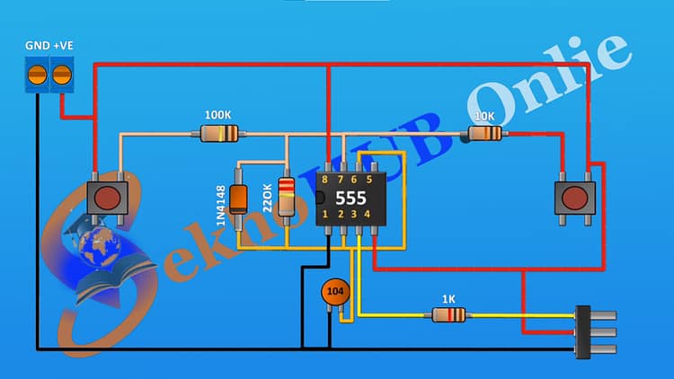
Circuit Diagram Explanation
This Servo Motor Tester circuit is based on the 555 Timer IC, configured in astable mode to produce PWM (Pulse Width Modulation) signals. Servo motors require a control pulse between 1ms and 2ms at 50Hz frequency to position their shaft precisely.
Here’s how the circuit works:
Pin 8 (VCC): Connected to +5V through the terminal block.
Pin 1 (GND): Connected to the ground terminal.
Pin 2 (Trigger): Connected to a push button via a 100kΩ resistor this helps start the PWM signal cycle.
Pin 3 (Output): Sends the PWM signal through a 1kΩ resistor to the 3-pin male header (Servo Signal).
Pin 4 (Reset): Connected to +5V via a 10kΩ resistor and reset push button.
Pin 5 (Control Voltage): Not used in this configuration (can be grounded with a 10nF capacitor for stability).
Pin 6 (Threshold) and Pin 2 (Trigger): Connected together through the 104 (0.1µF) capacitor to set the timing.
Pin 7 (Discharge): Connected with 100kΩ and 220kΩ resistors to set the duty cycle range.
1N4148 Diode (optional): Allows asymmetric charge/discharge timing for variable PWM duty control.
Output LED: Indicates PWM signal activity — helpful during testing.
When you press the left push button, the output PWM pulse width increases (servo rotates one direction).
When you press the right push button, the pulse width decreases (servo rotates the opposite direction).
By controlling the pulse width, you can move the servo shaft from 0° to 180°.
Download Circuit Diagram
Working Principle
A servo motor tester works by producing a variable PWM signal.
A short pulse (≈1ms) moves the servo to 0°.
A medium pulse (≈1.5ms) keeps it at 90° (center).
A long pulse (≈2ms) moves it to 180°.
The 555 timer generates these pulses continuously at about 50Hz, and the two buttons adjust the charging/discharging path of the capacitor, which in turn changes the pulse width.
So, pressing the buttons alters the RC time constant, thereby varying the servo’s position.
Step-by-Step Build Guide
Step 1.
Place the 555 Timer IC on the perf board.
Step 2.
Connect pin 1 of the 555 Timer to the ground rail on the perf board.
Step 3.
Connect pin 8 of the 555 Timer to the +5V power rail.
Step 4.
Connect a 0.1µF (104) capacitor between pin 2 (Trigger) and GND.
Step 5.
Connect pin 6 (Threshold) to pin 2 (Trigger).
Step 6.
Connect a 220kΩ resistor between pin 7 (Discharge) and pin 8 (+VCC).
Step 7.
Connect a 100kΩ resistor between pin 7 (Discharge) and pin 2 (Trigger).
Step 8.
(Optional) Connect a 1N4148 diode parallel to the 100k resistor (cathode toward VCC).
Step 9.
Connect a 10kΩ resistor between pin 4 (RESET) and +VCC.
Step 10.
Connect the reset push button from pin 4 to GND.
Step 11.
Connect the trigger push button between pin 2 and GND.
Step 12.
Connect an LED in series with a 1kΩ resistor from pin 3 (OUTPUT) to GND — this will blink when the servo moves.
Step 13.
Connect a 3-pin male header:
Pin 1 → Ground
Pin 2 → +5V
Pin 3 → Output from pin 3 of 555 Timer
This serves as the servo output connector.
Step 14.
Attach the 2-pin terminal block to the perf board for the +5V and GND power input.
Step 15.
Connect all jumper wires neatly to complete the circuit according to the schematic.
Step 16.
Finally, connect your servo motor to the 3-pin male header — signal to pin 3 output, VCC to +5V, and GND to ground.
Step 17.
Press the push buttons alternately to test the servo’s motion.
You’ll see the servo rotate clockwise or counterclockwise depending on the pulse width generated.
Testing the Circuit
Power the circuit using a regulated 5V DC supply.
Observe the LED blinking — this confirms the PWM signal output.
Connect your servo motor to the 3-pin header.
Press Button 1 — the servo moves in one direction.
Press Button 2 — the servo returns in the opposite direction.
Keep pressing to fine-tune the servo’s position.
This simple yet effective tester can handle most hobby servos like SG90, MG995, or MG996R.
Troubleshooting Tips
| Problem | Possible Cause | Solution |
|---|---|---|
| LED not blinking | Wrong wiring or short circuit | Double-check pin numbers and resistor placement |
| Servo not moving | Incorrect servo connection | Ensure correct signal, power, and ground wiring |
| Servo jittering | Unstable power supply | Use a separate 5V 2A supply for the servo |
| 555 gets hot | Reverse polarity or high current | Check polarity and avoid overloading the IC |
Applications
Testing servo motors before installation
Robotics and RC car calibration
Gimbal control testing
Educational demonstration of PWM generation
DIY automation system prototyping
Conclusion
By following this guide, you’ve successfully built a Servo Motor Tester using the 555 Timer IC.
It’s compact, reliable, and works independently without microcontrollers. The project demonstrates how a 555 Timer can generate PWM signals suitable for servo motor control.
You can extend this project further by adding a potentiometer for smooth rotation control or connecting a display to show the duty cycle percentage.
This circuit is ideal for hobbyists and engineers who frequently work with servos and need a quick testing solution.
Frequently Asked Questions (FAQs)
Q1. What voltage does the Servo Motor Tester operate on?
It works best on a 5V DC supply — the same as most hobby servo motors.
Q2. Can I use a potentiometer instead of push buttons?
Yes, you can replace the buttons with a 10k potentiometer for continuous rotation control.
Q3. Can this tester work with digital servos?
Yes, as long as the servo accepts standard 50Hz PWM signals, it will work perfectly.
Q4. Why is the LED used?
It acts as a PWM activity indicator, helping you visualize output changes when buttons are pressed.
Q5. What type of servos can I test?
You can test small and medium hobby servos like SG90, MG90S, MG995, MG996R, etc.
Q6. Can I use a 9V battery?
It’s not recommended for long use because servo motors draw more current. Use a 5V 2A regulated supply.
Q7. How do I know if my Servo Motor Tester is working correctly?
The LED should blink rapidly, and the servo should respond smoothly when you press either button.
Final Notes
This Servo Motor Tester circuit using a 555 Timer IC is an excellent learning project to understand PWM signal control and servo motor operation. It’s compact enough to fit on a small perf board and can be built in under an hour.
Experiment with different resistor values to change servo speed and response — and soon you’ll have a handy tool for all your robotics projects.