

This ESP32 IoT Home Automation Project allows you to control 4 outputs via WiFi efficiently. Using ESP32, relays, and optocouplers, this home automation project provides secure switching of 4 devices. The ESP32 IoT Home Automation Project includes BC547 transistors, 1N4007 diodes, LEDs, 1K resistors, 3-pin terminals, and a 7805 voltage regulator. With the ESP32 IoT Home Automation Project, you can control lights, fans, or other home appliances remotely.
This ESP32 IoT Home Automation Project guide explains the circuit, components, and step-by-step build instructions. Follow this ESP32 IoT Home Automation Project tutorial to make a reliable WiFi-controlled system. Implement this ESP32 IoT Home Automation Project and integrate it into your smart home setup seamlessly.
Introduction
Home automation is becoming increasingly popular, and controlling appliances via WiFi adds convenience and efficiency. This ESP32 IoT Home Automation Project allows you to control four devices remotely using a WiFi connection. It’s built with relays, optocouplers, and supporting electronics for safe and reliable operation.
With this project, you can automate lights, fans, or other small home appliances and integrate it with any IoT platform. The ESP32 provides built-in WiFi, making it an ideal microcontroller for home automation.
Materials for the Project
| S.No | Component | Quantity | Buy Link |
|---|---|---|---|
| 1 | ESP32 Board | 1 | Buy Link |
| 2 | 6V Relay | 4 | Buy Link |
| 3 | PC817 Optocoupler | 4 | Buy Link |
| 4 | BC547 NPN Transistor | 4 | Buy Link |
| 5 | 1N4007 Diode | 4 | Buy Link |
| 6 | 1K Resistor | 12 | Buy Link |
| 7 | LED | 4 | Buy Link |
| 8 | 3-Pin Terminal | 4 | Buy Link |
| 9 | 7805 Voltage Regulator | 1 | Buy Link |
Useful Tools
| Tool | Quantity | Purpose / Notes | Click & Buy |
|---|---|---|---|
| Soldering Iron Kit | 1 | For making permanent connections | Click & Buy |
| Solder Wire (60/40, 0.8mm) | 1 | Electrical soldering | Click & Buy |
| Wire Stripper & Cutter | 1 | Stripping jumper wires | Click & Buy |
| Mini Screwdriver Set | 1 | For module and relay terminal screws | Click & Buy |
| Multimeter | 1 | Testing voltages and continuity | Click & Buy |
| Hot Glue Gun (optional) | 1 | Securing components in place | Click & Buy |
| Small Pliers | 1 | Holding and bending wires | Click & Buy |
| Heat Shrink Tubing Set | 1 | Insulating exposed wires | Click & Buy |
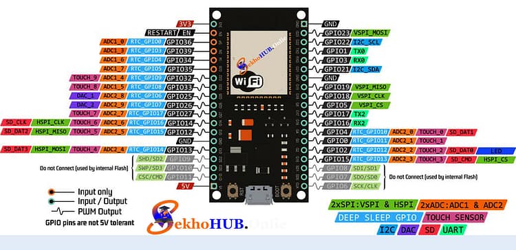
ESP32 Pinout.
| Pin | Type | Typical Use | Notes |
|---|---|---|---|
| 3V3 | Power | 3.3V supply to sensors, modules | Do not exceed 3.3V |
| GND | Power | Ground | Connect to all circuits for reference |
| EN (RST) | Control | Reset | Pull low to reset ESP32 |
| VIN | Power | Input voltage (5–12V) | Feeds internal regulator |
| GPIO 0 | Digital | Boot mode / general purpose | LOW at boot = flash mode |
| GPIO 1 (TX0) | UART | Serial TX | Avoid using for programming |
| GPIO 3 (RX0) | UART | Serial RX | Avoid using for programming |
| GPIO 2 | Digital | LED / general I/O | Has internal pull-up |
| GPIO 4 | Digital | Relay / sensor | Safe for outputs |
| GPIO 5 | Digital | Relay / LED | Standard digital I/O |
| GPIO 12 | Digital | SPI / output | Boot-sensitive |
| GPIO 13 | Digital | SPI / output | Can drive LEDs or relays |
| GPIO 14 | Digital | SPI / output | Safe for outputs |
| GPIO 15 | Digital | SPI / input | Boot-sensitive |
| GPIO 16, 17 | Digital | UART / output | Safe for general I/O |
| GPIO 18–23 | Digital | SPI / I2C / output | Multi-purpose, can drive relays |
| GPIO 25–27 | Digital / ADC / DAC | PWM / analog output | DAC pins for analog signals |
| GPIO 32–39 | Digital / ADC | Sensor inputs / analog | 3.3V max, input only for 34–39 |
| VP (GPIO 36), VN (GPIO 39) | Analog | ADC channels | Input-only, no pull-up |
| SDIO / SPI Pins | Digital | SD card / SPI | Shared functions with other GPIOs |
| SCL / SDA | I2C | Sensor communication | Default I2C pins (GPIO 22 = SCL, GPIO 21 = SDA) |
Notes:
PWM: Any GPIO except input-only pins can be used for PWM (relay control, LEDs).
ADC: GPIOs 32–39 for analog sensors.
Boot-sensitive Pins: GPIO 0, 2, 12, 15 – avoid driving high during boot unless intentional.
Relay/Output Control: Use GPIO 4, 5, 16, 17 for safe switching.
Voltage Limits: ESP32 GPIO pins are 3.3V max. Never exceed.
Circuit Diagram Explanation
The circuit allows the ESP32 to control 4 separate outputs safely through relays using optocouplers.
ESP32 GPIOs → connected to BC547 transistors through 1K resistors.
BC547 → drives the PC817 optocoupler to isolate the microcontroller from high voltage.
PC817 output → controls the 6V relay, which switches the home appliances.
Diodes (1N4007) → connected across relay coils to prevent back EMF damage.
LEDs → indicate the ON/OFF state of each relay.
7805 Regulator → provides a stable 5V supply to ESP32 if using a higher voltage DC source.
This configuration ensures that the ESP32 is protected while safely switching higher voltage devices.
Download Circuit Diagram

Step-by-Step Build Guide
Step 1.
First, mount the ESP32 on the breadboard or PCB and ensure its 5V and GND are properly connected.
Step 2.
Connect each GPIO pin (for example, GPIO 5, 18, 19, 21) to the base of BC547 through a 1K resistor.
Step 3.
Connect the collector of each BC547 transistor to the anode of PC817 optocoupler LED input. Connect the cathode to GND.
Step 4.
Connect the PC817 phototransistor output: collector goes to the relay’s input pin, emitter to GND.
Step 5.
Place 1N4007 diodes across each relay coil (cathode to +V, anode to coil pin) to protect against back EMF.
Step 6.
Connect LEDs with 1K resistors in series across each relay output to indicate the ON/OFF state.
Step 7.
Connect 3-pin terminals to relay outputs for connecting home appliances.
Step 8.
Power the ESP32 with 5V via 7805 regulator if using a 12V supply.
Step 9.
Upload the ESP32 code for WiFi control (using Blynk or a web server interface). Test each GPIO to ensure it switches the respective relay.
Applications
Home automation for lights, fans, and small appliances.
IoT-based energy management.
Remote control through smartphones or PC.
Smart home integration with sensors or voice assistants.
FAQs
Q1: Can I control appliances more than 6A using this setup?
A1: No, relays used here are 6V, typically rated for 5-10A. For higher current, use relays with higher ratings.
Q2: Can I use ESP8266 instead of ESP32?
A2: Yes, but ESP32 is preferred for multiple GPIOs and stable WiFi connection.
Q3: Do I need external power for relays?
A3: Yes, a 6V DC supply for relays is recommended; ESP32 cannot drive relays directly.
Q4: Can I use this system for AC appliances?
A4: Yes, but ensure proper isolation and use relays rated for AC voltage.
Q5: How do I control via smartphone?
A5: Use a Blynk app, or program ESP32 as a web server to control GPIOs over WiFi.
Conclusion
This ESP32 IoT Home Automation Project is a safe, reliable way to control 4 devices remotely. By combining ESP32, relays, optocouplers, and transistors, the system provides electrical isolation and clear visual feedback through LEDs. You can expand it further by adding sensors or integrating with voice assistants for a complete smart home experience.