

Introduction
The TDA7297 Amplifier IC module is a popular choice among hobbyists and electronics enthusiasts for building a robust DIY amplifier circuit. This tiny yet powerful chip provides dual channel audio amplifier IC functionality, making it perfect for driving small to medium-sized speakers with high efficiency. Operating as a Class AB amplifier IC, it offers a great balance between power and audio fidelity, especially when utilizing its low voltage audio amplifier chip capability, typically powered by a 12V amplifier supply. Its simplicity and compact nature allow for a clean TDA7297 PCB layout, making it the heart of any reliable compact stereo amplifier design for various audio applications.
Overview
Creating an audio circuit with the TDA7297 requires careful consideration of the TDA7297 amplifier setup, especially concerning the TDA7297 heatsink requirement and power integrity. This guide will walk you through the essential steps, from understanding the TDA7297 pinout explanation to the final TDA7297 speaker connection method. The IC is designed for 2×15W output amplifier performance, offering true stereo sound. We will cover the specific components needed to ensure a clean TDA7297 noise free amplifier operation, minimizing common issues and optimizing the TDA7297 home audio circuit for the best audio output quality.
What Is the TDA7297 IC?
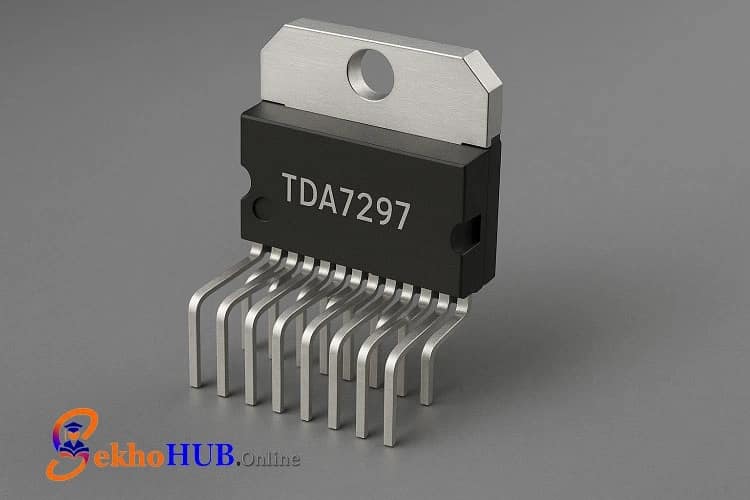
The TDA7297 IC is a monolithic integrated circuit from STMicroelectronics, primarily designed as a dual channel audio amplifier IC for use in small-scale consumer electronics and DIY projects. It operates in the Class AB audio amplification mode, which is known for its good linearity and low distortion. The chip is specifically intended for low voltage audio amplifier chip applications, typically functioning optimally with a 12V amplifier power supply. Key features include thermal shutdown protection and short-circuit protection, making it a reliable and robust component for a range of stereo audio projects.
How the TDA7297 Stereo Amplifier Works 💡
The TDA7297 functions as a complete stereo amplifier system on a chip. It takes a low-level audio input signal and, through its internal gain stages, amplifies both the left and right channels separately to deliver a high-power output capable of driving speakers. The TDA7297 gain settings are often fixed internally to simplify its use, but the addition of external components helps condition the input signal. Powering the chip via the TDA7297 power supply circuit enables the internal circuitry to efficiently convert the DC input voltage into an amplified AC output signal for the loudspeakers, achieving the 2×15W capability.
TDA7297 Pinout and Pin Functions
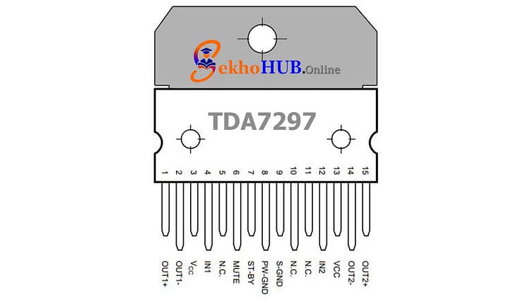
The TDA7297 is typically housed in a compact Multiwatt 15 package. Understanding the TDA7297 pinout explanation is crucial for proper wiring.
| Pin Number | Name | Function |
| 1 | SVR | Supply Voltage Rejection / Ripple filter |
| 3, 4 | IN L, IN R | Audio Input for Left and Right stereo channels |
| 5, 11 | GND | Ground / Common reference |
| 7, 9 | OUT L, OUT R | Audio Output for Left and Right speakers |
| 8 | VCC | Positive Power Supply Voltage (typically 6-18V DC) |
| 10 | Stand-by | Enables the chip (connected to VCC for operation) |
| 12 | Mute | Mutes the output (connected to GND for operation) |
| 13 | VSS | Negative Power Supply (internally connected to GND in single supply) |
The IC also features internal mute and standby functions controlled by Pins 10 and 12, allowing for professional control over the amplifier’s operation.
Components Required
| Component | Quantity | Buy Link |
|---|---|---|
| 47k Resistor | 12 | (BUY LINK) |
| 1M Resistor | 2 | (BUY LINK) |
| 4.7k Resistor | 2 | (BUY LINK) |
| 1k Resistor | 1 | (BUY LINK) |
| 5V Zener Diode | 1 | (BUY LINK) |
| 4.7µF Capacitor | 10 | (BUY LINK) |
| 470µF / 10V Capacitor | 1 | (BUY LINK) |
| 2200µF / 25V Capacitor | 1 | (BUY LINK) |
| 1N5408 Diode | 1 | (BUY LINK) |
| 7805 Voltage Regulator | 1 | (BUY LINK) |
| TDA7297 IC | 1 | (BUY LINK) |
| 222pF Capacitor | 2 | (BUY LINK) |
| BC548B Transistor | 2 | (BUY LINK) |
TDA7297 IC
- This low voltage audio amplifier chip is a compact module designed for stereo output. It delivers 2x15W of power, perfect for TDA7297 DIY audio project use. It features thermal shutdown protection and operates efficiently on a single DC input amplifier module voltage. Learn more .
PCB Layout
A good TDA7297 PCB layout is crucial for minimizing noise reduction in TDA7297 operation and ensuring optimal audio output quality.
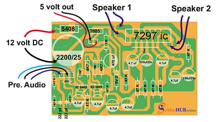
- Ground Plane: Use a thick or dedicated ground plane to handle the high current return path from the speaker outputs. This is key for a TDA7297 noise free amplifier.
- Input Filtering: Keep the passive components for the input filtering for audio IC close to the input pins to prevent external interference.
- Power Section: The main filter capacitor (2200\muF) in the TDA7297 power supply circuit should be placed as close to the IC‘s VCC and GND pins as possible.
- Heat Dissipation: Ensure the TDA7297 heatsink requirement is met by including a large copper area on the PCB connected to the tab, which should be properly mated with the external heatsink mounting for amplifier IC.
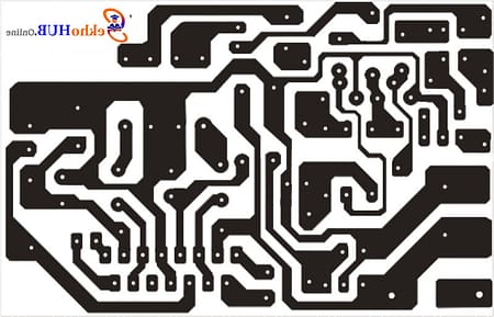
PCB Layout Dowload
Build Guide Step-by-Step
H3: Step 1
First, arrange all required components and verify the IC orientation before inserting it into the PCB.
Step 2
Now connect the input signal paths, ensuring left and right channels are properly routed.
Step 3
Attach the speaker terminals to the output section according to the TDA7297 speaker connection method.
Step 4
Add filtering capacitors to stabilize the TDA7297 power supply and reduce hum.
Step 5
Mount the voltage regulator and place the heatsink on the IC for thermal safety.
Step 6
Connect the 12V DC source and follow the TDA7297 wiring diagram to avoid reverse polarity.
Step 7
Test audio performance and complete enclosure fitting.
Common Problems and Troubleshooting
Distorted audio: Check TDA7297 board connections
Low output: Confirm supply voltage level
Noise: Improve grounding and input filtering
Overheating: Increase TDA7297 heatsink requirement
Safety Precautions ⚠️
Do not exceed the recommended voltage
Ensure proper heat dissipation
Use correct speaker impedance
Avoid touching live circuits
TDA7297 Advantages
Simple wiring
Low component count
Compact design
Affordable
Clean stereo output
Limitations ❌
- Heat: Requires a large heatsink for prolonged, high-power output, making the overall system less compact than a pure digital amplifier.
- Fixed Gain: The TDA7297 gain settings are often fixed, limiting flexibility unless a pre-amplifier is used.
- Output Power: While good for small speakers, the 2×15W output amplifier is not suitable for large, demanding home audio circuit setups.
Applications
Portable speaker units
Desktop stereo systems
DIY audio amplifiers
Embedded audio modules
Teaching/learning projects
FAQs
Q1: What is the difference between TDA7377 and TDA7297?
TDA7377 supports higher power, while TDA7297 is simpler and works well for small stereo systems.
Q2: How are components attached to a printed circuit board (PCB)?
They are soldered onto copper pads after being inserted through holes or placed on surface pads.
Q3: Which component can be used as an amplifier?
Transistors and audio amplifier ICs are commonly used as amplifiers.
Q4: What is TDA IC?
It refers to a family of audio amplifier ICs widely used in consumer electronics.
Q5: What does TDA stand for?
TDA stands for “Thomson Digital Audio.”
Q6: What does the IC stand for?
IC stands for “Integrated Circuit.”
Conclusion
The TDA7297 remains a practical and efficient choice for small audio circuits where simplicity and reliable stereo performance are required. Its low component count, built-in protections, and strong 2×15W capability make it ideal for compact DIY audio projects. With correct wiring, PCB layout, and heatsink handling, it delivers stable output for years of usage.