

Introduction
Building a Control RGB LED Using WiFi is a perfect entry point into the world of IoT Automation and Arduino Nano 33 IoT WiFi control. This guide demonstrates how to create Mobile controlled RGB LED lighting using the powerful features of the Arduino Nano 33 IoT board. By leveraging its integrated NINA-W102 WiFi module, we can enable RGB LED wireless control, allowing users to dynamically change the light color from anywhere via a simple web browser. This setup provides a practical example of Arduino IoT RGB lighting and how to use a Web server RGB LED Arduino setup to achieve seamless IoT based LED color control and remote color control.
Overview
This project centers on establishing a Webserver on the Arduino Nano 33 IoT to receive commands over Wireless communication for Control RGB LED using WiFi. The Microcontroller takes the incoming color values (Red, Green, Blue) from the user interface and converts them into appropriate PWM signal duty cycles. This PWM control RGB LED technique allows for over 16 million different colors, providing an effective IoT RGB LED control system. This setup is an excellent practical demonstration of the Arduino Nano 33 IoT WiFi example, showing how the NINA-W102 module facilitates wireless RGB LED control projects and Arduino IoT LED automation.
Components Required
| Quantity | Component | Description | Buy Link |
|---|---|---|---|
| 1 | Arduino Nano 33 IoT | Microcontroller board with built-in WiFi (ideal for IoT projects) | Buy Here |
| 1 | RGB LED Module (Common Cathode) | LED module with Red, Green, and Blue channels | Buy Here |
| 1 | Breadboard | For easy wiring and prototyping | Buy Here |
| 1 | Micro-USB Cable | To power and program the Arduino | Buy Here |
| Few | Jumper Wires | For making circuit connections | Buy Here |
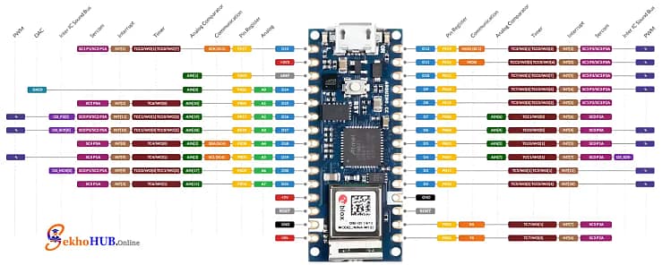
Arduino Nano 33 IoT
This compact Microcontroller is an excellent choice for IoT projects due to its small size, low power consumption, and integrated NINA-W102 module, which provides Wireless communication capabilities. It’s the brain that runs the HTTP web server and executes the PWM logic to achieve color control. It requires specific Arduino IDE configuration to use its powerful features effectively. .[Learn more]
RGB LED Module
An RGB LED combines three separate colored LEDs—Red, Green, and Blue—into a single package. By varying the brightness of each color using PWM, nearly any color in the spectrum can be generated. We use a Common cathode RGB LED, meaning the negative terminal (cathode) for all three LEDs is connected together and goes to ground.

Circuit Diagram
Build Guide Step-by-Step
Step 1. Prepare the Workspace
Place the Arduino Nano 33 IoT on a breadboard, ensure power is disconnected, and keep jumper wires and current limiting resistors ready.
Step 2. Connect the RGB LED
Insert the common cathode RGB LED into the breadboard. Connect the cathode pin to GND on the Arduino to establish a common reference.
Step 3. Wire the Red Channel
Connect Arduino pin D3 (PWM) to the Red (R) pin of the RGB LED through a resistor. This enables PWM control RGB LED for the red channel.
Step 4. Wire the Green Channel
Connect Arduino pin D6 (PWM) to the Green (G) pin using a resistor. This allows smooth brightness adjustment during RGB LED wireless control.
Step 5. Wire the Blue Channel
Connect Arduino pin D5 (PWM) to the Blue (B) pin through a resistor, completing the 3-channel PWM output setup.
Step 6. Power the Board
Attach the micro-USB cable to power the microcontroller and verify that no LED lights up unexpectedly.
Step 7. Configure WiFi Settings
Open Arduino IDE, select the correct board and port, and enter WiFi credentials for Arduino Nano 33 IoT WiFi control.
Step 8. Upload the Code
Compile and upload the sketch that creates a web server RGB LED Arduino interface for color adjustment.
Step 9. Test the Connection
Open the Serial Monitor, note the IP address, and access it from a browser to confirm the WiFi based RGB LED system is online.
Step 10. Verify Color Control
Use the web interface to change colors and confirm real-time IoT based LED color control response.
⚡ Important: You must place a Current limiting resistor (e.g., 330) in series with each of the Red, Green, and Blue LED pins before connecting them to the Arduino digital pins. This protects the LED from high current and ensures its longevity.
Arduino Code
#include <WiFiNINA.h>// WiFi credentialschar ssid[] = "Wi-Fi DCB367 2.4G";char pass[] = "tsTSP2SG";WiFiServer server(80);// RGB LED pins (PWM capable)const int redPin = 3;const int greenPin = 6; // swappedconst int bluePin = 5; // swappedint rValue = 0, gValue = 0, bValue = 0;void setup() {Serial.begin(9600);pinMode(redPin, OUTPUT);pinMode(greenPin, OUTPUT);pinMode(bluePin, OUTPUT);// Connect to WiFiwhile (WiFi.begin(ssid, pass) != WL_CONNECTED) {Serial.print(".");delay(1000);}Serial.println("\nConnected to WiFi");Serial.print("IP Address: ");Serial.println(WiFi.localIP());server.begin();}void loop() {WiFiClient client = server.available();if (client) {String request = client.readStringUntil('\r');client.flush();// Handle /setColor requestsif (request.indexOf("/setColor?") >= 0) {int rIndex = request.indexOf("r=");int gIndex = request.indexOf("g=");int bIndex = request.indexOf("b=");if (rIndex > 0 && gIndex > 0 && bIndex > 0) {rValue = request.substring(rIndex + 2, request.indexOf("&", rIndex)).toInt();gValue = request.substring(gIndex + 2, request.indexOf("&", gIndex)).toInt();bValue = request.substring(bIndex + 2, request.indexOf(" ", bIndex)).toInt();}// Update LEDanalogWrite(redPin, rValue);analogWrite(greenPin, gValue);analogWrite(bluePin, bValue);// Respond with OKclient.println("HTTP/1.1 200 OK");client.println("Content-Type: text/plain");client.println("Connection: close");client.println();client.println("OK");client.stop();return;}// Serve control webpageclient.println("HTTP/1.1 200 OK");client.println("Content-type:text/html");client.println("Connection: close");client.println();client.println("<!DOCTYPE HTML><html>");client.println("<head><meta name=\"viewport\" content=\"width=device-width, initial-scale=1\">");client.println("<script src=\"https://www.sekhohub.online/wp-content/litespeed/localres/aHR0cHM6Ly9jZG4uanNkZWxpdnIubmV0Lw==npm/@jaames/iro@5\"></script>");client.println("<style>");client.println("body{display:flex;flex-direction:column;justify-content:center;align-items:center;height:100vh;margin:0;font-family:Arial;}");client.println("h1{margin-bottom:20px;font-size:24px;color:#333;}");client.println("</style>");client.println("</head><body>");client.println("<h1>RGB LED Controller</h1>");client.println("<div id=\"picker\"></div>");client.println("<script>");client.println("var colorPicker=new iro.ColorPicker('#picker',{ width:300, color:'#ff0000'});");client.println("colorPicker.on('color:change',function(color){");client.println(" var r=color.rgb.r,g=color.rgb.g,b=color.rgb.b;");client.println(" var xhr=new XMLHttpRequest();");client.println(" xhr.open('GET','/setColor?r='+r+'&g='+g+'&b='+b,true);");client.println(" xhr.send();");client.println("});");client.println("</script>");client.println("</body></html>");client.stop();}}
Uploading & Testing
- Open Arduino IDE and install the WiFiNINA library.
- Replace the WiFi credentials (
ssidandpass) in the code with your own. - Upload the code to your Arduino Nano 33 IoT.
- Open the Serial Monitor (9600 baud) → copy the IP Address shown.
- Enter the IP in any web browser on the same WiFi network.
- Use the color picker to change the LED color in real-time.
Demo Output
- The webpage displays a circular color wheel.
- Selecting any color instantly updates the RGB LED.
- Smooth transitions are achieved using PWM on D3, D6, and D5.
Applications
Smart Ambient Lighting: Integrating the IoT RGB LED control system into home decor for mood lighting.
Notifications: Changing the LED color based on external IoT events (e.g., green for good weather, red for alerts).
Visual Feedback: Providing Wireless communication status updates in an IoT project.
Arduino IoT LED automation and scheduling through a separate Cloud service.
Prototyping Mobile controlled RGB LED applications for commercial products.
FAQs ❓
How to use Wi-Fi in Arduino?
WiFi is used by connecting the board to a network and running an HTTP server for communication.
Does the Arduino Nano 33 IoT have WiFi?
Yes, it includes built-in WiFi through the NINA-W102 WiFi module.
How can RGB LEDs be controlled efficiently using an Arduino?
By using PWM on three channels to mix colors smoothly.
What is the difference between Nano 33 IoT and BLE?
Nano 33 IoT supports WiFi, while BLE versions focus on Bluetooth communication.
Can Arduino Nano connect to WiFi?
Yes, Nano 33 IoT can directly connect to WiFi without external hardware.
What are the disadvantages of Arduino Nano?
Limited I/O pins and lower current output compared to larger boards.
Conclusion
This WiFi RGB LED Arduino project successfully demonstrates the integration of Arduino Nano 33 IoT WiFi control with a simple RGB LED. By establishing a basic HTTP web server and using 3-channel PWM output, we created an effective IoT based LED color control system, enabling a user to change LED color from mobile or any browser. This foundation can be expanded into more complex IoT Automation and Web server RGB LED Arduino solutions.