

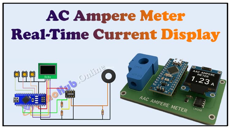
DIY AC Ampere Meter Arduino Project | Real-Time Current Display
This AC Ampere Meter Arduino project is a practical DIY electronics build designed for measuring AC current with precision. Using the AC Ampere Meter Arduino approach, you can monitor electrical loads in real time. The AC Ampere Meter Arduino project makes use of a current transformer sensor, Arduino Nano, and OLED display. By building this AC Ampere Meter Arduino circuit, hobbyists and students can learn AC measurement principles.
This AC Ampere Meter Arduino system is suitable for home, lab, and educational use. With the AC Ampere Meter Arduino method, real-time values are displayed instantly. This AC Ampere Meter Arduino project provides accuracy and reliability. Learning AC measurement becomes easier with this AC Ampere Meter Arduino DIY project. Whether beginner or experienced, this AC Ampere Meter Arduino tutorial will guide you step by step.
Introduction
Measuring AC current is essential in electrical and electronics applications, especially when monitoring loads, appliances, or lab experiments. Traditional multimeters work fine, but for continuous monitoring and DIY automation, a digital AC Ampere Meter Arduino Project is far more useful.
In this project, we will design a simple yet effective AC Ampere Meter using:
Arduino Nano (brain of the system)
CT Sensor (100A/50mA, 2000:1 ratio) (for current measurement)
LM358 IC (for signal conditioning)
OLED Display (for real-time current readings)
This project is affordable, accurate, and a perfect learning experience for electronics students and hobbyists.
Materials for the Project
| S.No | Component | Quantity | Buy Link |
|---|---|---|---|
| 1 | Arduino Nano | 1 | Buy Link |
| 2 | OLED Display (0.96” I2C, 128×64) | 1 | Buy Link |
| 3 | LM358 Operational Amplifier IC | 1 | Buy Link |
| 4 | CT Sensor 100A/50mA (2000:1) | 1 | Buy Link |
| 5 | 47Ω Resistor | 1 | – |
| 6 | 10K Resistors | 2 | – |
| 7 | 2-Pin Terminal Block | 1 | – |
| 8 | Perf Board | 1 | – |
| 9 | Jumper Wires | As req. |
Useful Tools
| Tool | Quantity | Purpose / Notes | Click & Buy |
|---|---|---|---|
| Soldering Iron Kit | 1 | For making permanent connections | Click & Buy |
| Solder Wire (60/40, 0.8mm) | 1 | Electrical soldering | Click & Buy |
| Wire Stripper & Cutter | 1 | Stripping jumper wires | Click & Buy |
| Mini Screwdriver Set | 1 | For module and relay terminal screws | Click & Buy |
| Multimeter | 1 | Testing voltages and continuity | Click & Buy |
| Hot Glue Gun (optional) | 1 | Securing components in place | Click & Buy |
| Small Pliers | 1 | Holding and bending wires | Click & Buy |
| Heat Shrink Tubing Set | 1 | Insulating exposed wires | Click & Buy |
Download Circuit Diagram

Circuit Diagram & Working Explanation
The working principle is simple:
The CT Sensor senses the AC current flowing through the wire.
The output of the CT is a small AC signal (millivolts).
The 47Ω burden resistor converts this current signal into a measurable voltage.
The LM358 IC amplifies and conditions the signal for the Arduino.
The Arduino Nano reads the analog input and calculates the RMS current value.
The OLED Display shows the measured current in amperes.
⚡ Note: This project is isolated because of the CT sensor, so it’s safe for low-voltage measurements, but always take proper precautions when handling mains AC.
Step-by-Step Guide to Build
Step 1: Circuit Connections
Connect CT sensor output across the 47Ω resistor.
Feed this voltage into LM358 amplifier circuit.
Connect the amplifier output to Arduino Nano A0 pin.
Connect OLED display via I2C pins (A4 = SDA, A5 = SCL).
Provide Arduino Nano with 5V DC supply.
Use 2-pin terminal block to connect the load wire through CT sensor.
Step 2: Arduino Code Upload
Arduino Code
Use the Arduino IDE.
Install Adafruit SSD1306 and Adafruit GFX libraries for OLED.
Write a code to:
Read analog values from A0.
Convert into RMS current using CT ratio.
Display real-time current on OLED.
Step 3: Testing
Pass a known load (like a 100W bulb) through the CT sensor.
Check if the OLED shows the expected current (~0.45A for 100W/220V).
Calibrate if needed by adjusting burden resistor or calibration factor in code.
Applications
Monitoring household AC loads
Laboratory experiments
DIY energy meter projects
Current monitoring in solar inverters and UPS
❓ FAQs
Q1: Can I measure DC current with this project?
No, CT sensors only measure AC current. For DC, you’d need a Hall-effect sensor like ACS712.
Q2: What is the maximum current measurable?
With a 100A/50mA CT, you can measure up to 100A safely.
Q3: Can I use LCD instead of OLED?
Yes, a 16×2 LCD with I2C module works as well.
Q4: Is the circuit safe for beginners?
Yes, because the CT sensor isolates the Arduino from high-voltage AC.