

AC Volt Ampere Meter Arduino Project with OLED Display
This AC Volt Ampere Meter Arduino Project is a practical DIY electronics build for measuring AC voltage and current using Arduino Nano, LM358 IC, and a 100A/50mA CT sensor. In this project, you’ll learn how to assemble the circuit on a perf board, wire the OLED display, and calibrate the current transformer for accurate readings.
The AC Volt Ampere Meter Arduino Project is designed for hobbyists, students, and engineers who want to monitor electrical loads in real time. With clear circuit explanation, step-by-step assembly guide, and a detailed Bill of Materials, you’ll be able to replicate this project with ease. This AC Volt Ampere Meter Arduino Project helps you understand the working of current sensors and op-amps in AC measurement systems. Explore this AC Volt Ampere Meter Arduino Project to enhance your skills in electronics measurement and monitoring.
Introduction
Monitoring voltage and current in AC circuits is crucial for both beginners and professional engineers. Whether you are testing an electrical load, measuring power consumption, or troubleshooting a home appliance, having a Volt Ampere Meter saves time and gives accurate insights.
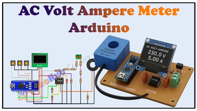
In this project, we’ll design an Arduino-based AC Volt Ampere Meter using an Arduino Nano, an OLED display, and a 100A/50mA current transformer (CT). The LM358 IC acts as an amplifier to process the CT output, while a set of resistors forms a potential divider network for voltage sensing. The real-time data will be displayed on the OLED screen.
By the end of this guide, you’ll understand the circuit, build your own working prototype, and learn how to calibrate it for accuracy.
With clear circuit explanation, step-by-step assembly guide, and a detailed Bill of Materials, you’ll be able to replicate this project with ease. This AC Volt Ampere Meter Arduino Project helps you understand the working of current sensors and op-amps in AC measurement systems. Explore this AC Volt Ampere Meter Arduino Project to enhance your skills in electronics measurement and monitoring.
Materials for the Project
| S.No | Component | Quantity | Description | Buy Link |
|---|---|---|---|---|
| 1 | Arduino Nano | 1 | Microcontroller board | Buy Link |
| 2 | OLED Display 0.96″ | 1 | I2C 128×64 display | Buy Link |
| 3 | Current Transformer (CT) | 1 | 100A/50mA (2000:1 ratio) | Buy Link |
| 4 | LM358 IC | 1 | Dual Op-Amp IC | Buy Link |
| 5 | Resistor 47Ω | 1 | Burden resistor for CT | – |
| 6 | Resistor 2.2kΩ | 1 | Voltage divider | – |
| 7 | Resistor 4.7kΩ | 1 | Voltage divider | – |
| 8 | Resistor 10kΩ | 3 | Biasing network | – |
| 9 | Resistor 470kΩ | 6 | Voltage sensing divider | – |
| 10 | 2-Pin Terminal Block | 2 | For AC input/output connection | – |
| 11 | Perf Board | 1 | For circuit assembly | – |
| 12 | Jumper Wires | Several | For connections | – |
Useful Tools
| Tool | Quantity | Purpose / Notes | Click & Buy |
|---|---|---|---|
| Soldering Iron Kit | 1 | For making permanent connections | Click & Buy |
| Solder Wire (60/40, 0.8mm) | 1 | Electrical soldering | Click & Buy |
| Wire Stripper & Cutter | 1 | Stripping jumper wires | Click & Buy |
| Mini Screwdriver Set | 1 | For module and relay terminal screws | Click & Buy |
| Multimeter | 1 | Testing voltages and continuity | Click & Buy |
| Hot Glue Gun (optional) | 1 | Securing components in place | Click & Buy |
| Small Pliers | 1 | Holding and bending wires | Click & Buy |
| Heat Shrink Tubing Set | 1 | Insulating exposed wires | Click & Buy |
Download Circuit Diagram

Circuit Diagram Explanation
The circuit consists of two main measurement sections:
AC Voltage Sensing
A resistor divider network (six 470kΩ resistors + supporting resistors) scales down the high AC mains voltage to a safe level for Arduino.
This scaled signal is then processed and mapped into Arduino’s ADC input.
To ensure safety, all resistors must have high voltage ratings.
AC Current Sensing
The 100A/50mA CT sensor produces a small current proportional to the load current.
A 47Ω burden resistor converts this current into a voltage.
The signal is weak, so the LM358 op-amp amplifies it before feeding into the Arduino.
Microcontroller & Display
Arduino Nano reads both signals using its ADC channels.
Code processes the RMS values and calculates Voltage (V) and Current (A).
Results are displayed on the OLED display in real-time.
For detailed theory on CT sensors, you can check OpenEnergyMonitor CT Sensors Guide.
Step-by-Step Building Guide
Step 1: Prepare Components
Gather all components listed in the BOM.
Use a perf board for soldering to make the project durable.
Step 2: Assemble Voltage Divider
Connect six 470kΩ resistors in series.
Add supporting resistors (2.2kΩ, 4.7kΩ, and 10kΩ) to scale the AC mains voltage down to 5V peak.
Output goes to Arduino analog pin A0.
Step 3: Wire the CT Sensor
Connect the CT sensor in series with the AC load.
Connect its secondary to the 47Ω burden resistor.
Feed the output to the LM358 op-amp for amplification.
Send the processed signal to Arduino analog pin A1.
Step 4: Power and Ground
Use Arduino Nano’s 5V & GND to power the LM358 and OLED.
Double-check common ground connections.
Step 5: Connect the OLED Display
Use I2C pins:
A4 → SDA
A5 → SCL
Power OLED from Arduino’s 5V & GND.
Step 6: Upload Arduino Code
Arduino Code
Open Arduino IDE.
Install required libraries:
Adafruit_GFX.h
Adafruit_SSD1306.h
Upload the sketch to Arduino Nano.
The code will read analog inputs, calculate RMS voltage and current, and display them on OLED.
Step 7: Testing & Calibration
Connect a 60W bulb or fan as a test load.
Compare readings with a commercial multimeter.
Adjust calibration constants in the code for accuracy.
Applications
Measuring AC load current and voltage.
Testing small appliances.
Educational demonstrations.
Power monitoring for DIY projects.
Safety Precautions
⚠️ Important: You are dealing with AC mains voltage.
Always insulate exposed connections.
Use proper rated resistors.
Test with low loads first.
Work on a wooden table and wear insulated shoes.
FAQs
1. Can I also measure power (Watt) with this project?
Yes. By multiplying Voltage × Current (and considering phase angle), you can calculate Real Power. For basic use, you can extend the code.
2. Why use LM358 IC?
The LM358 acts as a signal amplifier to boost the weak CT sensor output before it enters Arduino.
3. Can I replace OLED with LCD?
Yes, a 16×2 LCD (I2C module) can also be used, but OLED gives a clearer, compact display.
4. How accurate is this meter?
Accuracy depends on calibration. By comparing with a digital multimeter and adjusting constants, you can achieve ±2% accuracy.
5. Can I measure DC current with this setup?
No. CT sensors only work with AC. For DC, use a Hall-effect sensor like ACS712.