

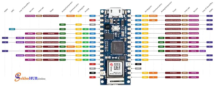
The Arduino Nano 33 IoT is a versatile IoT development board that contains a powerful built-in IMU sensor, making it ideal for the Arduino Nano 33 IoT IMU project. This guide will focus on creating an Arduino Nano 33 IoT Motion Monitoring, where we use the internal LSM6DS3 accelerometer gyroscope to capture motion data and display it immediately. By pairing the board with an OLED SSD1306 Arduino display, we can create a self-contained unit for real-time motion data display. This setup is a fantastic way to learn about Arduino motion sensor visualization and the capabilities of this tiny but powerful IoT development board.
Overview Arduino Nano 33 IoT Motion Monitoring
Our goal is to create a complete embedded systems project that effectively uses the onboard LSM6DS3 IMU for real-time visualization. The Arduino Nano 33 IoT acts as the central processor, reading the raw acceleration values and angular velocity from the LSM6DS3 accelerometer gyroscope. This motion data is then sent via the I2C communication protocol to the compact OLED SSD1306 display, resulting in the OLED display real-time motion data. This demonstration of IMU data visualization Arduino is highly relevant for applications like wearable motion tracking and robotics motion analysis, providing instant visual feedback on axis movement and orientation change.
What You Will Learn.
By completing this project, you will gain practical knowledge in:
- Interfacing the built-in IMU sensor of the Arduino Nano 33 IoT sensor interfacing.
- Utilizing the LSM6DS3 library to read accelerometer and gyroscope data.
- Implementing I2C OLED display Arduino I2C communication for the SSD1306 OLED.
- Creating sensor data visualization techniques for real-time display of motion data.
- The fundamental process of motion tracking using Arduino Nano 33 IoT for various embedded motion sensing projects.
Components Required
| Quantity | Component | Description | Buy Link |
| 1 | Arduino Nano 33 IoT | Microcontroller with internal LSM6DS3 IMU | [Buy Link] |
| 1 | SSD1306 OLED Display 128×64 | I2C interface, monochrome OLED | [Buy Link] |
| Various | Jumper wires | For connections between Arduino and OLED | [Buy Link] |
| 1 | Breadboard | Optional, for prototyping | [Buy Link] |
Arduino Nano 33 IoT
This board is a compact, 3.3V-operating IoT development board that includes the LSM6DS3 accelerometer gyroscope directly on the PCB. This eliminates the need for external wiring for the IMU itself. It’s perfect for low-power motion sensing and handling the I2C communication required for the OLED display, forming a complete Arduino-based motion system. [Learn more]
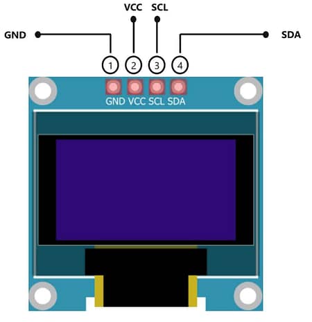
SSD1306 OLED Display 128×64
The OLED SSD1306 is a small, high-contrast, self-illuminating display that uses minimal power. Its simple I2C interface makes it ideal for projects where power and size are critical. It acts as the output screen for the IMU data visualization Arduino and the OLED SSD1306 motion display, making the motion data instantly understandable. [Learn more]
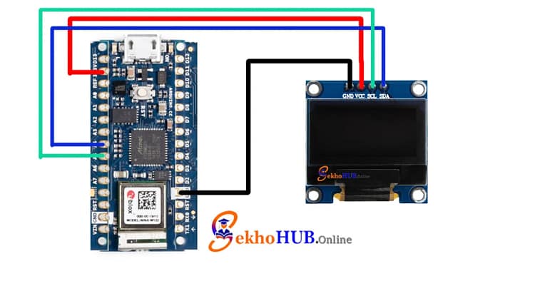
Circuit Diagram
The main connections are between the Arduino Nano 33 IoT and the external OLED SSD1306 display. The LSM6DS3 is already connected internally via the Arduino‘s internal I2C communication.
Build Guide Step-by-Step 🛠️
Step 1: Wiring Connections
The SSD1306 OLED Display 128×64 uses the standard I2C communication pins on the Arduino Nano 33 IoT. The I2C protocol requires only two data wires: SDA (Serial Data) and SCL (Serial Clock).
| OLED Pin | Arduino Nano 33 IoT Pin | Connection Type |
| VCC | 3.3V | Power Supply |
| GND | GND | Ground |
| SDA | A4 | I2C Data Line |
| SCL | A5 | I2C Clock Line |
This simple I2C OLED display Arduino connection forms the real-time visualization output for your project.
Step 2: Arduino IDE Configuration and Library Setup
To successfully compile and run the code for the LSM6DS3 accelerometer gyroscope project, you need two essential libraries:
- Arduino_LSM6DS3: This library handles the communication and data retrieval from the built-in IMU sensor. Install it via the Library Manager.
- Adafruit SSD1306: This library is used to control the OLED SSD1306 display. Install both the Adafruit SSD1306 and the required Adafruit GFX library.
Arduino Code 💻
The Arduino sketch initializes the LSM6DS3 IMU and the OLED display. In the main loop, it continuously reads the acceleration values and angular velocity (motion data). This raw data is then formatted and written to the OLED SSD1306 motion display, creating the Arduino IMU data visualization. Crucially, the code handles the sensor calibration offsets and updates the display quickly for effective real-time visualization of the axis movement and orientation change.
#include <Wire.h>#include <Arduino_LSM6DS3.h>#include <Adafruit_GFX.h>#include <Adafruit_SSD1306.h>#include <math.h>#define SCREEN_WIDTH 128#define SCREEN_HEIGHT 64Adafruit_SSD1306 display(SCREEN_WIDTH, SCREEN_HEIGHT, &Wire, -1);float angle = 0; // Radar sweep angleconst int radarRadius = 30;const int centerX = SCREEN_WIDTH/2;const int centerY = SCREEN_HEIGHT/2;// Motion detection thresholdconst float motionThreshold = 0.15;void setup() {Serial.begin(9600);// Initialize IMUif (!IMU.begin()) {Serial.println("Failed to initialize IMU!");while(1);}// Initialize OLEDif (!display.begin(SSD1306_SWITCHCAPVCC, 0x3C)) {Serial.println("SSD1306 allocation failed");for (;;);}display.clearDisplay();display.setTextSize(1);display.setTextColor(SSD1306_WHITE);display.setCursor(10, 0);display.println("Motion Visualizer");display.display();delay(800);}void loop() {float xAcc, yAcc, zAcc;bool motionDetected = false;if (IMU.accelerationAvailable()) {IMU.readAcceleration(xAcc, yAcc, zAcc);// Calculate overall acceleration magnitudefloat magnitude = sqrt(xAcc*xAcc + yAcc*yAcc + zAcc*zAcc);// Detect motionmotionDetected = magnitude > motionThreshold;display.clearDisplay();if(motionDetected){// Display motion detected textdisplay.setTextSize(2);display.setCursor(10, SCREEN_HEIGHT/2 - 10);display.println("Motion Detected!");} else {// Radar animationdisplay.drawCircle(centerX, centerY, radarRadius, SSD1306_WHITE);display.drawCircle(centerX, centerY, radarRadius-5, SSD1306_WHITE);int x = centerX + radarRadius * cos(angle);int y = centerY + radarRadius * sin(angle);display.drawLine(centerX, centerY, x, y, SSD1306_WHITE);angle += 0.1;if(angle > 2*3.14159) angle = 0;// Draw radar centerdisplay.fillCircle(centerX, centerY, 2, SSD1306_WHITE);}display.display();}delay(30);}
Applications
The Arduino Nano 33 IoT motion visualizer can be applied in various fields:
- Wearable Motion Tracking: Monitoring physical activity, steps, and posture in wearable motion tracking devices.
- Robotics Motion Analysis: Measuring the tilt and rotation of robot joints for precise robotics motion analysis.
- Simple Tilt/Shock Logger: Detecting motion detection and recording the magnitude of impacts.
- Gaming Controller: Using the IMU data to control characters or actions in video games.
- Low-power motion sensing applications for long-term battery-powered monitoring.
FAQs ❓
Can Arduino Nano run an OLED display?
Yes, the Arduino Nano (including the Arduino Nano 33 IoT) can easily run an OLED SSD1306 display using the I2C communication protocol.
How to connect an OLED display to Arduino?
The OLED display is connected to the Arduino via the I2C communication pins: SDA to A4 and SCL to A5 on the Arduino Nano 33 IoT.
Do Arduino Nano 33 IoT have gyrometers in them?
Yes, the Arduino Nano 33 IoT has a built-in IMU sensor (LSM6DS3) which contains both an accelerometer and a gyroscope.
- What is the difference between Nano 33 IoT and ble?
The Nano 33 IoT focuses on Wi-Fi and IoT capabilities, while the Nano 33 BLE focuses on Bluetooth Low Energy Wireless communication for simple sensor interfacing. What are the disadvantages of Arduino Nano?
The older Arduino Nano has limited processing power; however, the Arduino Nano 33 IoT addresses this with a more powerful Microcontroller and built-in IMU sensor.
Is Arduino Nano better than ESP32?
The Arduino Nano 33 IoT is better for simplicity and seamless integration into the Arduino ecosystem and has a built-in IMU sensor, while the ESP32 often offers more processing power.
Conclusion
This project provides a comprehensive guide to utilizing the powerful LSM6DS3 accelerometer gyroscope embedded in the Arduino Nano 33 IoT. By successfully implementing the I2C OLED display Arduino connection, we created a functional Motion visualization using Arduino Nano 33 IoT system. This Arduino IMU data visualization project is a valuable step for anyone interested in low-power motion sensing and sensor data visualization within an IoT context.