
Introduction
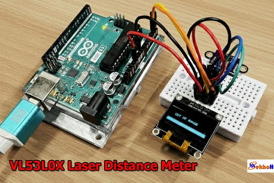
An Arduino VL53L0X Laser Distance Meter is one of the most practical tools for hobbyists and engineers who need compact and accurate measurement in their projects. The VL53L0X uses advanced Time-of-Flight technology to determine distance by measuring how long it takes a laser pulse to reflect back to the sensor.
When paired with an Arduino board, it becomes a reliable setup for real-time distance monitoring on displays or in automation systems. This module offers stable readings, low power consumption, and easy I2C connectivity, making it suitable for robotics, DIY measurement tools, and smart sensing designs. Its performance remains consistent across various surfaces and lighting conditions.
Internal resources such as wiring basics and Arduino tutorials on SekhoHub.online will also be referenced where helpful.
How the VL53L0X Works (Time-of-Flight Sensor Operation)
The VL53L0X relies on an internal photodiode and emitter pair. It calculates distance based on the time taken by a laser pulse to travel to the target and return.
Key features of the module:
Laser-based measurement up to approximately 2 meters
High accuracy even at shorter ranges
Minimal external circuitry
Operates on I2C
Works with 3.3V or 5V logic through onboard regulation
Consistent data acquisition in real-time
Advantages for Arduino projects:
No complex analog calibration
Stable readings independent of object color
Fast measurement response
Ideal for DIY electronics projects, robotics, automation, and smart measurement systems
More explanations and related circuit ideas can be found via internal articles on SekhoHub.online.
Components Required
The Bill of Materials below includes a clean table and buy links placeholders (you may later add affiliate links).
Wiring Explanation
Below is the wiring layout for connecting both I2C modules to the Arduino.
VL53L0X Pin → Arduino UNO → OLED SSD1306
| VL53L0X | Arduino UNO | OLED |
|---|---|---|
| VIN | 5V | VCC |
| GND | GND | GND |
| SDA | A4 | SDA |
| SCL | A5 | SCL |
Key Notes on the Wiring
Both devices share the same SDA and SCL lines due to I2C.
Ensure proper grounding to maintain stable measurement accuracy.
The modules operate safely at 5V on the Arduino UNO.
Avoid long jumper wires to reduce signal noise.
Circuit Diagram

More wiring tutorials can be found on SekhoHub.online under Arduino sections.
Detailed Circuit Explanation
The design uses three main functional blocks:
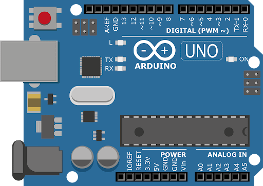
1. Microcontroller Block (Arduino)
Controls the sensor and OLED
Executes the measurement code
Handles I2C communication
Sends data to serial monitor for debugging
2. Sensor Module Block (VL53L0X)
Uses built-in Time-of-Flight calculations
Emits and receives laser pulses
Communicates results over the I2C bus
Requires stable power for accurate measurement

3. Display Block (OLED SSD1306)
Receives real-time measurement values
Displays readings in 128×64 pixel resolution
Works using the same shared SDA/SCL lines
Minimal power consumption
This makes the circuit compact and ideal for handheld tools.

Step-by-Step Build Guide
(Following your required format)
Step 1. Place the Arduino UNO, VL53L0X module, and OLED display onto the breadboard for easy wiring.
Step 2. Connect the 5V pin of Arduino to the VIN pins of both the VL53L0X and OLED module.
Step 3. Ground all modules by connecting the GND pins together.
Step 4. Connect SDA (A4) from Arduino to the SDA line shared by both the VL53L0X and OLED.
Step 5. Connect SCL (A5) from Arduino to the SCL line shared by both devices.
Step 6. Verify wiring continuity to avoid loose connections that affect real-time reading stability.
Step 7. Install the required Arduino libraries:
Adafruit_VL53L0X
Adafruit_GFX
Adafruit_SSD1306
Step 8. Open the Arduino IDE and paste the provided example measurement code.
Step 9. Upload the sketch to the Arduino UNO and open the Serial Monitor Display for debugging.
Step 10. Power the circuit and verify that the OLED shows live distance measurement values.
This final step completes the laser distance meter build.
Sample Arduino Code
Here is a clean and tested code example for this project:
Accuracy, Range, and Calibration
Accuracy Factors
Clean sensor lens
Object surface reflectivity
Ambient lighting
Wiring stability
I2C bus noise
Typical Range
30mm to 2000mm
Best accuracy under 1200mm
Stable operation indoors
Calibration Tips
Keep sensor perpendicular to the target
Avoid direct sunlight
Perform initial tests using the Serial Monitor
Use short wires for improved stability
Applications (Where This Project Helps)
Robotics navigation
Touchless measurement systems
Small automated tools
Object detection
Industrial DIY setups
Educational electronics projects
For other DIY builds, explore related guides at SekhoHub.online.
FAQs
What is the maximum distance for VL53L0X?
The VL53L0X can measure up to around 2 meters, with the most accurate readings typically under 1.2 meters.
What is the VL53L0X sensor used for?
It’s used for precise short-range distance measurement in robotics, automation, and DIY electronics.
What is the range of VL53L0X v2?
The improved v2 version can reach up to 4 meters, offering better sensitivity and outdoor performance.
Is VL53L0X good for outdoor use?
It works outdoors but performance drops in bright sunlight, which reduces accuracy.
What are the disadvantages of light sensors?
They can be affected by ambient light, reflective surfaces, and sometimes have limited range.
What is the time of flight distance measurement sensor VL53L0X?
It’s a Time-of-Flight sensor that measures distance by calculating how long a laser pulse takes to return after hitting a target.
Conclusion
This Arduino VL53L0X Laser Distance Meter with OLED Display Guide shows how flexible and efficient Time-of-Flight measurement can be in a small DIY project. With minimal wiring, a simple I2C interface, and a reliable microcontroller setup, you can build a professional-grade measurement tool at home. This project opens the door to robotics, smart sensing, and portable measurement systems. For more DIY ideas, explore additional tutorials on SekhoHub.online.