

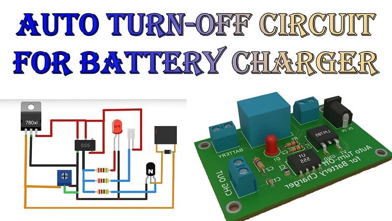
How to Make an Auto Turn-Off Circuit for Battery Charger Using a 555 Timer IC
Battery overcharging not only shortens battery life but also poses safety risks. Whether you’re charging Li-ion, lead-acid, or NiMH batteries, an automatic cut-off feature is essential. In this blog, we’ll show you how to make an automatic turn-off circuit for a battery charger using the popular 555 timer IC.
This project is ideal for electronics beginners, hobbyists, and even professionals who want a simple yet reliable solution for smart battery charging.
✅ What Is an Auto Turn-Off Circuit?
An auto turn-off circuit for a battery charger is designed to disconnect the charging source from the battery once it reaches a full charge. It helps:
Prevent overcharging
- Enhance battery lifespan
- Avoid safety issues (e.g., overheating, swelling)
- Reduce power wastage
This circuit automatically senses the battery voltage and stops the charging process when it exceeds a predefined voltage level.
✅ Why Use a 555 Timer IC?
The 555 Timer IC is a widely used and versatile integrated circuit capable of generating precise time delays and oscillations. For this project, we will use it in comparator mode (monostable or bistable) to detect the battery voltage level and trigger a relay or transistor to cut off the charging path.
Why the 555 IC?
- Low cost and easily available
- Can work with a wide voltage range (4.5V–15V)
- Simple to configure for detection or switching tasks
- Can directly drive a relay or transistor
- Perfect for DIY automation circuits
✅ How the Circuit Works
- The core principle is voltage sensing and switching. Here’s how the auto cut-off circuit functions.
- The battery is connected to the charging source through a relay or transistor.
- A voltage divider monitors the battery voltage and feeds it to the threshold and trigger pins of the 555 timer IC.
- Once the battery voltage exceeds the set threshold (e.g., 12.6V for a 12V battery), the 555 timer changes output state.
- This output disconnects the charger by shutting off the relay and transistor.
- A manual reset button can be added to restart the charging process.
Materials for the Project
Here’s a list of components you’ll need for building the auto cut-off circuit:
1- 1X 555 TIMER IC
2- 1X 8 PIN BASE
3- 1X LM7805 EGURATOR
4- 1X 12V RELAY
5- 1X 10K OHM VARIABLE RESISTOR
6- 1X C945 TRANSISTOR 100 UF CAPACITOR
7- 1X 1N4007 DIODE 8- 1X RED LED
9- 1X GREEN LED
10- 2X 220 OHM RESISTORS
11- 1X 10K OHM RESISTOR
12- 1X 47 UF CAPACITOR
13- 1X PIECE OF VERO BOARD
14- JUMPER WIRES
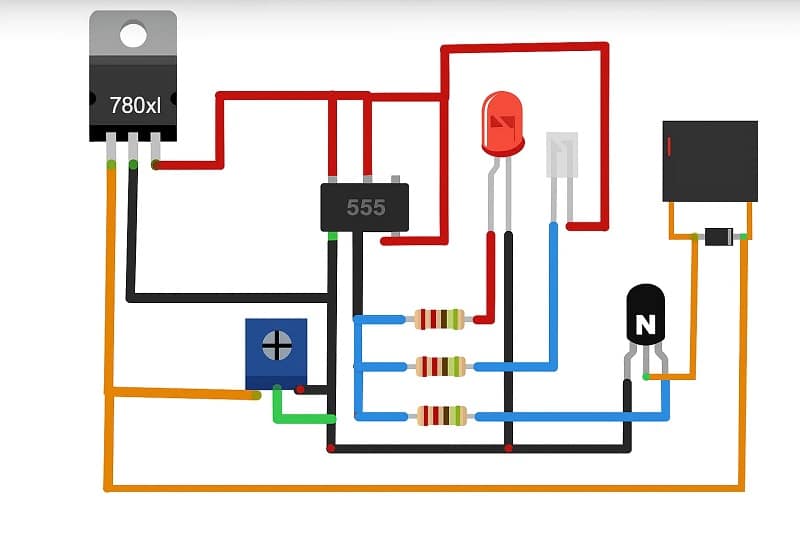
Download Circuit Diagram
⚠️ Note: Since I can’t generate images directly here, you can visualize or design this using Fritzing or Proteus. Alternatively, I can provide a downloadable version on request.
Block Description:
- Input Section: Charger connected to battery through relay.
- Section of Sensing: Voltage divider connected to 555 IC pins 6 and 2.
- Control Section: 555 timer connected in comparator mode.
- Output Section: Pin 3 drives the base of a transistor, which controls the relay.
✅ Step-by-Step Building Instructions
Let’s build this circuit step by step:
- Set up the voltage divider.
- Connect two resistors (or a variable resistor) in series across the battery terminals.
- Tap the junction of the resistors to pins 6 (Threshold) and 2 (Trigger) of the 555 Timer.
- Adjust the values so that this voltage reaches around 2/3 of the supply voltage when the battery is full.
- Configure the 555 Timer
- Connect Pin 1 to Ground.
- Pin 8 to Vcc (12V).
- Pin 4 (Reset) is tied to Vcc to disable reset mode.
- Pin 5 is left open or connected to a 10 nF capacitor to ground for noise reduction.
- Output Switching Section
- Pin 3 (Output) is connected to the base of an NPN transistor through a 1 kΩ resistor.
- The collector of the transistor is connected to one terminal of the relay coil.
- The emitter is grounded.
- A flyback diode (1N4007) is placed across the relay coil for protection.
- Relay Configuration
- The relay’s common is connected to the charger’s output.
- The normally closed (NC) terminal is connected to the battery positive terminal.
- The relay remains active while the battery is charging.
- When the battery is full, the relay deactivates and breaks the circuit.
- (Optional) Add Status LEDs
- Connect a green LED to indicate charging.
- A red LED lights up when the battery is full, controlled by the output pin.
✅ Testing the Circuit
After building the circuit:
- Utilizing either a fixed voltage divider or a variable resistor, set the battery voltage threshold.
- Connect the battery to the circuit.
- Observe the relay operation:
- Below the threshold, the relay remains ON.
- When the battery is fully charged, the relay turns off.
4. The cut-off point can be fine-tuned by adjusting the reference voltage.
✅ Applications
This auto turn-off circuit is ideal for:
- DIY battery charger stations
- Solar battery charging systems
- Power banks
- Emergency lighting setups
- Battery-powered robotics or IoT devices
✅ Advantages of This Circuit
- ✅ Simple design using readily available components
- ✅ Cost-effective solution for smart charging
- ✅ No microcontroller required
- ✅ Safe for most rechargeable batteries
- ✅ Easy to modify for different voltage levels
✅ Conclusion
Creating an auto turn-off circuit for battery chargers using a 555 timer IC is a fantastic way to upgrade your DIY charging setup. It prevents overcharging, saves energy, and enhances battery performance—all using a simple, low-cost design.
Whether you’re a beginner in electronics or an experienced maker, this project is a must-have addition to your toolkit. Plus, the 555 timer IC opens doors to endless automation and control circuits in future projects.
If you enjoyed this tutorial, stay tuned for more DIY electronics projects, circuits, and beginner guides. Got a question or improvement idea? Drop a comment below or contact us directly!