

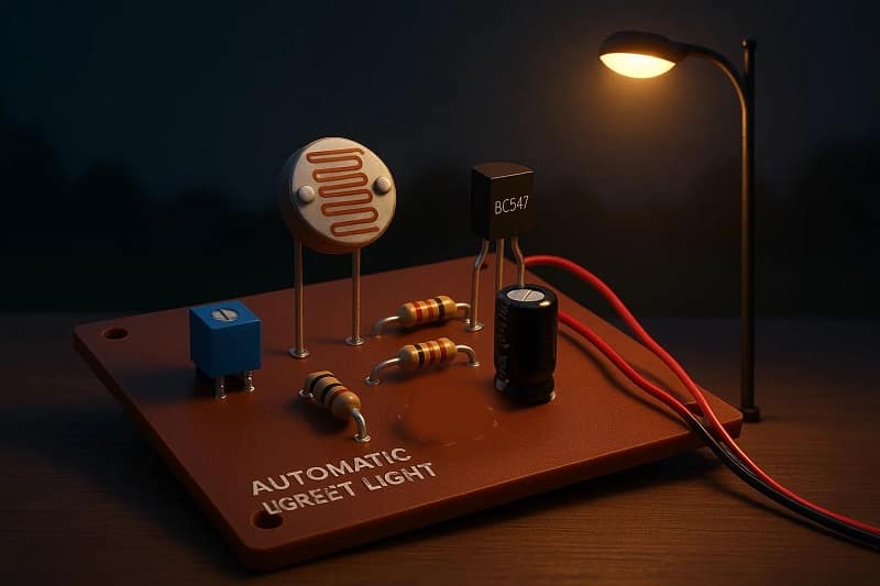
Automatic Street Night Light Circuit Using LDR.
Introduction.
This project finds its applications in places such as streets, gardens, and other public places. So, in today’s tutorial, we will go over a step-by-step process of designing an automatic street night light circuit using an LDR (light-dependent resistor). The main component of this automatic street light is an LDR, or a light-dependent resistor. LDRs are electronic components that are sensitive to light intensity. Its behavior is similar to a photocell that works on the principle of photoconductivity. This passive component is basically a resistor whose resistance value decreases when the intensity of light increases. It is not uncommon for the values of resistance of an LDR or photoresistor to be at several MΩ in darkness and then to fall to a few hundred ohms in bright light.
Materials for the Project
- 1X LDR 5mm
- 2X NPN transistor BC547
- 3X LED 5mm/3.5V
- 2X Resistor 1K, 100K Resistor
- 1x DC Battery 12V
- 1x Jumper Wires
BC547 Transistor Pinout.

✅ Pin Details
Pin 1 – Collector (C): Connects to the load or positive side of the circuit.
Pin 2 – Base (B): Controls the transistor; a small current here turns the transistor ON.
Pin 3 – Emitter (E): Connects to ground or the negative side of the circuit.
Download Circuit Diagram

Circuit Explanation
Here’s how the components work together:
The LDR and a 10kΩ resistor form a voltage divider. This sends a varying voltage to the transistor’s base depending on light intensity.
During daylight, the LDR gets light, its resistance drops, and the voltage at the transistor’s base stays too low to turn it ON.
At night, when the LDR’s resistance rises, the base gets enough voltage to activate the transistor.
When the transistor turns ON, it energizes the relay, closing the circuit for the street lamp, which turns ON.
A flyback diode is added across the relay coil to protect the transistor from voltage spikes.
Power Supply Tips
Use a 5V or 12V regulated adapter depending on your relay coil voltage.
If powering directly from AC, include a step-down transformer and a voltage regulator to keep things safe.
✅ Applications
Automatic outdoor lighting for homes, farms, or streets
Energy-saving lighting systems
School and college mini projects
Motion-triggered lighting (with optional PIR sensor add-on)
Working Explanation
This circuit powers an array of three LEDs when the intensity of the light on the LDR decreases. During the daytime, the light intensity on the LDR increases, decreasing the resistance value of the LDR. This diminishes the strength of the control signal on the base of transistor Q1, and the LEDs remain off.
As the night falls, the light intensity over the LDR decreases, subsequently increasing the resistance of the LDR. This allows the control signal to flow to the base of the BC547 transistor. The output from Q1 acts as a control signal for the base terminal of the transistor Q2. The collector output from transistor Q2 then triggers the LED array to glow.