

BJT Tester Circuit | DIY NPN and PNP Transistor Testing Tool 8 Steps
The BJT Tester is a simple yet highly useful DIY electronics project for checking NPN and PNP transistors. With this BJT Tester, you can easily determine whether a transistor is working or faulty by using just LEDs, resistors, and push buttons. The BJT Tester circuit is designed to light up an LED when the transistor under test is functioning correctly.
This project helps students, hobbyists, and engineers quickly test components before using them in larger circuits. Building a BJT Tester is cost-effective and can be done on a breadboard or PCB with minimal components. Whether you’re new to electronics or experienced, this BJT Tester project provides a practical way to understand transistor operation. Learn step-by-step how to make your own BJT Tester and simplify your component testing process with this handy BJT Tester tool.
Introduction
In electronics, transistors are the backbone of most modern circuits. From amplification to switching applications, Bipolar Junction Transistors (BJTs) are widely used in almost every electronic device. But before using a transistor in any project, you must ensure it is in working condition. Faulty transistors can cause circuit failures, wasted time, and even component damage.
That’s where a BJT Tester Circuit comes in handy.
This DIY BJT Tester allows you to check NPN and PNP transistors quickly using just a few basic components such as resistors, LEDs, and push buttons. When a transistor is inserted into the tester and the switch is pressed, an LED lights up if the transistor is functioning properly. If the LED does not glow, the transistor is faulty.
What is a BJT Tester?
A BJT Tester is a small electronic circuit designed to check the health of bipolar junction transistors. It tells you if the transistor is:
Good (working properly)
Shorted (Collector-Emitter or Base short)
Open (not conducting)
Leaky (partially faulty)
The BJT Tester Circuit uses LEDs as indicators. When you apply base current to the transistor through a push button, the transistor switches ON, and the LED lights up. If the LED fails to glow, the transistor is either damaged or not connected correctly.
Materials for the Project
| Component | Value / Type | Quantity | Description / Notes | Buy Link |
|---|---|---|---|---|
| Resistor | 220 Ω | 2 | Current limiting resistors for LEDs | Buy 220Ω Resistors |
| Resistor | 470 Ω | 2 | Base current limiting resistors | Buy 470Ω Resistors |
| Resistor | 10 kΩ | 2 | Pull-up / pull-down resistors | Buy 10kΩ Resistors |
| Resistor | 8.2 kΩ | 2 | Biasing resistors | Buy 8.2kΩ Resistors |
| LED (Red) | 5mm | 2 | Indicator LEDs for NPN & PNP test | Buy 5mm Red LEDs |
| Push Button Switch | Momentary (SPST) | 2 | Used to apply base current | Buy Push Button Switch |
| Transistor Socket | 3-pin (E-B-C) | 2 | For inserting NPN and PNP transistors | Buy Transistor Sockets |
| Connector Block | 2-pin / 3-pin | 4 | Screw terminals for easy wiring | Buy Terminal Blocks |
| DC Power Supply | 5V (USB or Adapter) | 1 | Power source for the circuit | Buy 5V Adapter |
| General Purpose PCB | – | 1 | For assembling components | Buy General Purpose PCB |
| Jumper Wires | Male-to-Male | As needed | For connections | Buy Jumper Wires |
Useful Tools
| Tool | Quantity | Purpose / Notes | Click & Buy |
|---|---|---|---|
| Soldering Iron Kit | 1 | For making permanent connections | Click & Buy |
| Solder Wire (60/40, 0.8mm) | 1 | Electrical soldering | Click & Buy |
| Wire Stripper & Cutter | 1 | Stripping jumper wires | Click & Buy |
| Mini Screwdriver Set | 1 | For module and relay terminal screws | Click & Buy |
| Multimeter | 1 | Testing voltages and continuity | Click & Buy |
| Hot Glue Gun (optional) | 1 | Securing components in place | Click & Buy |
| Small Pliers | 1 | Holding and bending wires | Click & Buy |
| Heat Shrink Tubing Set | 1 | Insulating exposed wires | Click & Buy |
Download Circuit Diagram

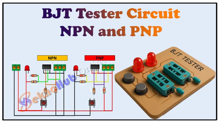
Circuit Diagram Explanation
The circuit is divided into two identical parts:
Left Side → NPN Transistor Testing
Right Side → PNP Transistor Testing
✦ Power Supply
A 5V DC supply powers the entire circuit.
Common ground is shared by both NPN and PNP sections.
✦ LED Indicators
Each section has one LED.
When a good transistor is placed and base current is applied, the LED lights up.
✦ Resistors
220 Ω: Protects LED from excess current.
470 Ω: Limits base current.
10 kΩ: Ensures base stability when button is not pressed.
8.2 kΩ: Works as part of the biasing network.
✦ Push Button
Each transistor section has a push button.
When pressed, it sends current to the Base, turning ON the transistor.
✦ NPN Section (Left)
Insert the NPN transistor into the socket (E-B-C).
When the button is pressed, base current flows.
If the transistor is good, current flows from Collector to Emitter, and the LED lights up.
✦ PNP Section (Right)
Insert the PNP transistor into the socket (E-B-C).
When the button is pressed, base current flows in opposite polarity.
If the transistor is good, current flows from Emitter to Collector, and the LED lights up.
Step-by-Step Construction Guide
Follow these steps to build the BJT Tester Circuit:
Step 1: Gather Components
Collect all resistors, LEDs, push buttons, sockets, and PCB.
Step 2: Prepare the PCB or Breadboard
If you are prototyping, use a breadboard.
For permanent use, solder components onto a general-purpose PCB.
Step 3: Place the Resistors
Insert the 220Ω resistors in series with LEDs.
Place the 470Ω resistors at the transistor’s base input.
Connect 10kΩ as pull-up/pull-down for stability.
Add 8.2kΩ for base biasing.
Step 4: Add the LEDs
Connect LEDs in series with the 220Ω resistor.
Ensure correct polarity: Anode to +VCC, Cathode towards transistor output.
Step 5: Insert Push Buttons
Connect push buttons between the base biasing network and VCC.
Each button controls one transistor section.
Step 6: Add Transistor Sockets
Mount two 3-pin sockets (E-B-C).
Left socket → NPN test.
Right socket → PNP test.
Step 7: Wiring & Power
Connect everything as per the circuit diagram.
Provide +5V supply and GND connections.
Step 8: Testing the Circuit
Insert a known good NPN transistor (e.g., BC547) → Press button → LED should glow.
Insert a known good PNP transistor (e.g., BC557) → Press button → LED should glow.
Try a faulty transistor → LED will not glow.
How to Test Transistors with BJT Tester
Good NPN transistor: LED glows when button pressed.
Good PNP transistor: LED glows when button pressed.
Shorted transistor: LED glows continuously, even without pressing the button.
Open/faulty transistor: LED does not glow at all.
Leaky transistor: LED glows weakly or flickers.
⚡ Advantages of BJT Tester Circuit
Simple and low-cost
Works for both NPN and PNP transistors
Instant visual feedback with LEDs
Helps detect shorted, open, or leaky transistors
Portable and DIY-friendly
❓ FAQs
1. Can this tester check all types of BJTs?
Yes, it can test most small-signal NPN and PNP transistors. However, it may not work accurately for very high-power transistors.
2. Can I use a higher supply voltage?
The circuit is designed for 5V. Using higher voltages may burn LEDs or transistors.
3. What if the LED stays ON without pressing the button?
This usually means the transistor is shorted (collector-emitter short).
4. Can I use different resistor values?
Yes, but they should be close to the given values (220Ω, 470Ω, 10k, 8.2k). Otherwise, biasing may not work properly.
5. Why do we need both NPN and PNP sections?
Because NPN and PNP transistors conduct in opposite directions. Separate sections allow testing of both types.
6. How is this different from digital transistor testers?
This is a basic DIY tester with LEDs for visual feedback. Digital testers give detailed parameters like HFE, leakage current, etc., but are more expensive.
7. Can I build it on breadboard first?
Yes, breadboard is recommended for quick testing before making a permanent PCB.
Conclusion
The BJT Tester Circuit is a practical and simple DIY project for electronics enthusiasts, students, and engineers. It allows quick testing of both NPN and PNP transistors using minimal components. With just resistors, LEDs, and push buttons, you can build a reliable transistor tester at home.
This project not only helps you save time by detecting faulty transistors but also improves your understanding of BJT operation.
If you regularly work with electronics, building a BJT Tester will be one of the most useful tools on your workbench.