

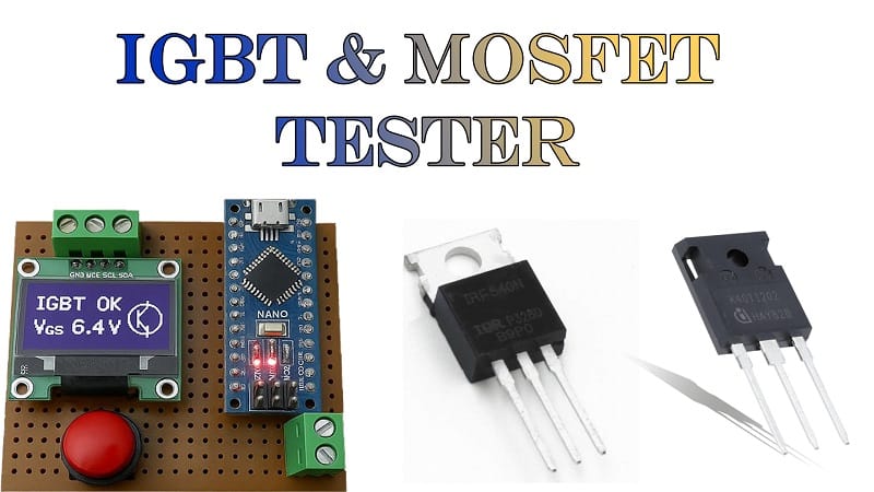
Build a Powerful IGBT and MOSFET Tester Using Arduino Nano in 5 Steps
This guide shows you how to build an IGBT and MOSFET Tester using Arduino Nano. An IGBT and MOSFET Tester is essential for electronics enthusiasts, allowing quick testing of both IGBT and MOSFET devices. By making your own IGBT and MOSFET Tester, you save time and money compared to manual testing. This IGBT and MOSFET Tester project uses Arduino Nano, OLED display, PC817 optocoupler, and resistors to identify device health.
Building an IGBT and MOSFET Tester step by step ensures beginners can follow easily. Our DIY IGBT and MOSFET Tester provides accurate results and is portable for labs or workshops. Using this IGBT and MOSFET Tester, you can test gate switching and performance effectively. The IGBT and MOSFET Tester is ideal for students, engineers, and hobbyists. Start today and create your own IGBT and MOSFET Tester project at home.
Introduction
When working with power electronics, IGBTs (Insulated Gate Bipolar Transistors) and MOSFETs (Metal Oxide Semiconductor Field-Effect Transistors) are the backbone of circuits such as inverters, motor drivers, and SMPS systems. However, before reusing or installing one, it’s crucial to test whether the device is functional.
Instead of complex bench setups, this Arduino-based IGBT and MOSFET Tester allows you to check:
Gate triggering behavior
Switching performance
Basic on/off functionality
Materials for the Project
| S. No. | Component | Quantity | Description | Buy Link |
|---|---|---|---|---|
| 1 | Arduino Nano | 1 | Main controller | Buy Link |
| 2 | OLED Display (0.96”) | 1 | For test result display | Buy Link |
| 3 | Push Button | 1 | Start test input | Buy Link |
| 4 | Boost Converter | 1 | Provides required gate drive voltage | Buy Link |
| 5 | PC817 Optocoupler | 1 | Isolation for safe gate triggering | Buy Link |
| 6 | 1kΩ Resistor | 2 | Current limiting | Buy Link |
| 7 | 2.2kΩ Resistor | 1 | Biasing resistor | Buy Link |
| 8 | 4.7kΩ Resistor | 1 | Pull-down resistor | Buy Link |
| 9 | 47kΩ Resistor | 1 | Gate control | Buy Link |
| 10 | 100kΩ Resistor | 1 | Biasing resistor | Buy Link |
| 11 | 220kΩ Resistor | 1 | Pull-up resistor | Buy Link |
| 12 | 2-Pin Terminal Block | 1 | For device under test | Buy Link |
| 13 | 3-Pin Terminal Block | 1 | For IGBT/MOSFET connection | Buy Link |
| 14 | Perf Board | 1 | Circuit assembly | Buy Link |
| 15 | Jumper Wires | As needed | Connections | Buy Link |
Arduino Nano Pinout.

The Arduino Nano has 30 pins in total (15 on each side). These include Power, Digital I/O, Analog, Communication, and Special pins.
Power Pins
VIN (Pin 30): Input voltage (7–12V) from external supply.
5V (Pin 27): Regulated 5V output from onboard regulator.
3.3V (Pin 17): Regulated 3.3V output (max 50mA).
GND (Pins 8, 14, 20, 22, 29): Ground pins.
RESET (Pin 28): Used to reset the microcontroller.
Digital I/O Pins
D0 (RX) & D1 (TX): UART communication.
D2 – D13: General-purpose digital I/O.
PWM Pins: D3, D5, D6, D9, D10, D11 (used for analogWrite).
SPI Pins:
D10 → SS (Slave Select)
D11 → MOSI (Master Out Slave In)
D12 → MISO (Master In Slave Out)
D13 → SCK (Serial Clock)
Analog Input Pins
A0 – A7: 8 analog inputs (10-bit ADC resolution).
A4 → SDA (I²C data line).
A5 → SCL (I²C clock line).
Special Pins
AREF (Pin 21): Reference voltage for ADC.
ICSP (6-pin header): Used for programming ATmega328P with an external programmer.
D13: Connected to onboard LED.
Circuit Diagram Explanation
The tester works as follows:
The Arduino Nano sends control signals to the PC817 optocoupler, providing isolation between the logic side and the IGBT/MOSFET under test.
A boost converter supplies higher gate drive voltage (10–15V typical) since MOSFETs and IGBTs require more than Arduino’s 5V.
The push button triggers the test routine.
The OLED display shows the device status: Good, Leaky, or Faulty.
Resistors are used for gate biasing, pull-up, and current limiting.
This setup ensures both safe operation and reliable testing.
Step-by-Step Guide
Step 1: Assemble the Circuit
Place the Arduino Nano and OLED display on the perf board.
Wire the PC817 optocoupler between Arduino’s PWM pin and gate terminal.
Connect the boost converter to supply the required gate drive.
Add the terminal blocks for easy device insertion.
Step 2: Write the Arduino Code
Complete Arduino Code (OLED + Debounce + Auto-Scaling)
#include <Wire.h>
#include <Adafruit_GFX.h>
#include <Adafruit_SSD1306.h>
// ———- Display ———-
#define SCREEN_WIDTH 128
#define SCREEN_HEIGHT 64
#define OLED_RESET -1
Adafruit_SSD1306 display(SCREEN_WIDTH, SCREEN_HEIGHT, &Wire, OLED_RESET);
// ———- Pins ———-
const uint8_t PIN_BUTTON = 2; // Active-LOW, internal pullup
const uint8_t PIN_GATE = 9; // Drives PC817 LED (through series resistor)
const uint8_t PIN_SENSE = A0; // From divider at the test node
// ———- ADC / Divider / Voltage Model ———-
const float VREF = 5.0f; // Nano analog reference (default AVcc)
const uint16_t ADC_MAX = 1023;
const float R_TOP = 100000.0f; // 100k from test node to A0 (top)
const float R_BOT = 10000.0f; // 10k from A0 to GND (bottom)
// Estimate Vboost (12V) by sampling with gate OFF, assuming pull-up via load
// You may also hardcode VBOOST if you prefer:
// const float VBOOST_FIXED = 12.0f; // uncomment to force
// #define USE_FIXED_VBOOST
// ———- Test Timing ———-
const uint16_t PULSE_MS_ON = 300; // Gate HIGH duration per test
const uint16_t PULSE_MS_OFF = 300; // Recovery time
const uint8_t N_SAMPLES = 15; // Samples per state
const uint16_t DEBOUNCE_MS = 30; // Button debounce
// ———- Thresholds (% of Vboost) ———-
const float TH_GOOD_ON_MAX = 0.15f; // <15% of Vboost at test node when ON
const float TH_GOOD_OFF_MIN = 0.70f; // >70% of Vboost at test node when OFF
const float TH_LEAKY_LOW = 0.30f; // 30% boundary
const float TH_LEAKY_HIGH = 0.70f; // 70% boundary
// ———- Utils ———-
float adcToVolts(uint16_t adc)
{
return (adc * VREF) / ADC_MAX; // Volts at A0 pin
}
float a0ToNodeVolts(float v_a0)
{
// Vnode = Va0 * (1 + Rtop/Rbot)
return v_a0 * (1.0f + (R_TOP / R_BOT));
}
uint16_t readMedianADC(uint8_t pin, uint8_t n)
{
// Simple median-of-n (n should be odd; if even, we just pick lower mid)
static uint16_t buf[25]; // supports up to 25 samples
if (n > 25) n = 25;
for (uint8_t i = 0; i < n; i++) {
buf[i] = analogRead(pin);
delay(2);
}
// insertion sort
for (uint8_t i = 1; i < n; i++) {
uint16_t key = buf[i];
int8_t j = i – 1;
while (j >= 0 && buf[j] > key) {
buf[j+1] = buf[j];
j–;
}
buf[j+1] = key;
}
return buf[n/2];
}
bool waitButtonPress()
{
// Wait for a stable falling edge (HIGH->LOW)
if (digitalRead(PIN_BUTTON) == LOW) {
delay(DEBOUNCE_MS);
if (digitalRead(PIN_BUTTON) == LOW) {
// Wait for release before returning to avoid repeat
while (digitalRead(PIN_BUTTON) == LOW) { delay(5); }
delay(DEBOUNCE_MS);
return true;
}
}
return false;
}
void drawHeader(const char* line2 = nullptr)
{
display.clearDisplay();
display.setTextSize(1);
display.setTextColor(SSD1306_WHITE);
display.setCursor(0, 0);
display.println(F(“IGBT & MOSFET Tester”));
if (line2) display.println(line2);
display.display();
}
void showResult(const char* label, float v_on, float v_off, float vboost)
{
display.clearDisplay();
display.setTextSize(1);
display.setCursor(0, 0);
display.println(F(“Test Complete”));
display.println();
display.print(F(“Result: “));
display.println(label);
display.print(F(“Vboost: “));
display.print(vboost, 2);
display.println(F(” V”));
display.print(F(“V_OFF: “));
display.print(v_off, 2);
display.println(F(” V”));
display.print(F(“V_ON : “));
display.print(v_on, 2);
display.println(F(” V”));
// Percentages
float p_off = (v_off / vboost) * 100.0f;
float p_on = (v_on / vboost) * 100.0f;
display.print(F(“%OFF : “));
display.print(p_off, 0);
display.println(F(“%”));
display.print(F(“%ON : “));
display.print(p_on, 0);
display.println(F(“%”));
display.display();
}
void setup()
{
pinMode(PIN_BUTTON, INPUT_PULLUP);
pinMode(PIN_GATE, OUTPUT);
pinMode(PIN_SENSE, INPUT);
digitalWrite(PIN_GATE, LOW);
display.begin(SSD1306_SWITCHCAPVCC, 0x3C);
display.clearDisplay();
display.setTextSize(1);
display.setTextColor(SSD1306_WHITE);
display.setCursor(0, 0);
display.println(F(“IGBT & MOSFET Tester”));
display.println(F(“Insert DUT & Press Btn”));
display.display();
delay(1200);
}
float estimateVboost()
{
#ifdef USE_FIXED_VBOOST
return VBOOST_FIXED;
#else
// Measure OFF-state node voltage; if DUT is not short/leaky,
// this approaches the pull-up (boost) voltage via load.
uint16_t adc = readMedianADC(PIN_SENSE, N_SAMPLES);
float v_a0 = adcToVolts(adc);
float v_node = a0ToNodeVolts(v_a0);
// Clamp to reasonable range to avoid division by near-zero later
if (v_node < 3.0f) v_node = 3.0f; // minimal estimate
if (v_node > 30.0f) v_node = 30.0f; // cap (divider limit)
return v_node;
#endif
}
void loop()
{
drawHeader(F(“Press button to test”));
if (!waitButtonPress()) {
delay(10);
return;
}
drawHeader(F(“Testing…”));
// 1) OFF measurement (gate LOW)
digitalWrite(PIN_GATE, LOW);
delay(PULSE_MS_OFF);
uint16_t adc_off = readMedianADC(PIN_SENSE, N_SAMPLES);
float v_off_a0 = adcToVolts(adc_off);
float v_off_node = a0ToNodeVolts(v_off_a0);
// Estimate Vboost from OFF state (or use fixed)
float vboost = estimateVboost();
// 2) ON measurement (gate HIGH)
digitalWrite(PIN_GATE, HIGH);
delay(PULSE_MS_ON);
uint16_t adc_on = readMedianADC(PIN_SENSE, N_SAMPLES);
float v_on_a0 = adcToVolts(adc_on);
float v_on_node = a0ToNodeVolts(v_on_a0);
// Return gate LOW
digitalWrite(PIN_GATE, LOW);
delay(PULSE_MS_OFF);
// Normalize to Vboost
float r_off = v_off_node / vboost; // expected near 1.0 if device fully OFF
float r_on = v_on_node / vboost; // expected near 0.0 if device fully ON
// Classify
const char* verdict = “LEAKY”;
bool good_off = (r_off >= TH_GOOD_OFF_MIN);
bool good_on = (r_on <= TH_GOOD_ON_MAX);
bool faulty_off = (r_off < TH_LEAKY_LOW);
bool faulty_on = (r_on > TH_LEAKY_HIGH);
if (good_off && good_on) {
verdict = “GOOD”;
} else if (faulty_off || faulty_on) {
verdict = “FAULTY”;
} else {
verdict = “LEAKY”;
}
showResult(verdict, v_on_node, v_off_node, vboost);
// Hint to user
delay(1500);
display.setCursor(0, 56);
display.print(F(“Press btn to retest”));
display.display();
// Wait for release+press cycle before next loop iteration
while (!waitButtonPress()) { delay(20); }
}
Initialize OLED with I2C.
Configure the button pin as input.
Generate a gate pulse when the button is pressed.
Monitor the collector/emitter (or drain/source) response.
Display results on OLED.
Step 3: Upload & Test
Connect Arduino Nano via USB.
Upload the sketch.
Insert a MOSFET or IGBT into the test socket.
Press the button → OLED shows device condition.
Step 4: Verify Results
A working MOSFET/IGBT will switch cleanly (OLED shows “GOOD”).
A leaky or shorted device will show faulty.
Step 5: Mount in Enclosure (Optional)
For professional use, mount the circuit in a small box with external terminals for easy testing.
Applications
Quick lab testing of MOSFETs and IGBTs.
Useful for electronics repair technicians.
Great educational tool for students learning power electronics.
FAQs
Q1. Can this tester measure Rds(on) of MOSFETs?
Not directly, but you can detect faulty/shorted devices.
Q2. What’s the maximum voltage this tester can handle?
Limited by boost converter and optocoupler (typically 12–15V).
Q3. Can I test both N-channel and P-channel MOSFETs?
Yes, with slight code modifications.
Q4. Is isolation necessary with PC817?
Yes, it ensures Arduino is safe from high side voltages.
Q5. Can I expand this project to test BJT transistors?
Yes, but the code logic needs adjustment for base-emitter control.