

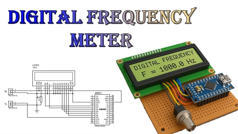
How to Make a Digital Frequency Meter Using Arduino Nano and 16×2 LCD
How to make digital frequency meter projects is a popular topic for electronics hobbyists. In this guide, we explain how to make digital frequency meter using b, a 16×2 LCD, and basic components like a 1K resistor, breadboard, and jumper wires. This tutorial on how to make digital frequency meter will walk you through the working principle, circuit connections, and programming steps.
Whether you’re a student or a DIY enthusiast, learning how to make digital frequency meter can help you understand frequency measurement and LCD interfacing. We cover each step so you can easily follow along on how to make digital frequency meter without confusion. From wiring to testing, every detail of how to make digital frequency meter is covered clearly. Start your own Arduino project today with our complete guide on how to make digital frequency meter.
Introduction
Measuring frequency is an essential task in electronics—whether you’re troubleshooting an oscillator, working on a radio receiver, or designing signal-processing circuits. A digital frequency meter is a tool that counts how many times a signal repeats per second (Hertz).
In this guide, I’ll walk you through how to make a digital frequency meter using Arduino Nano and a 16×2 LCD. It’s a simple but practical project that’s perfect for learning about signal measurement and microcontroller interfacing.
Materials for the Project (Digital Frequency Meter)
| No. | Component | Quantity | Description |
| 1 | Arduino Nano | 1 | Main microcontroller to process and measure frequency |
| 2 | 16×2 LCD | 1 | Display to show measured frequency |
| 3 | 1K Resistor | 1 | Used as a pull-down resistor for stable input |
| 4 | Breadboard | 1 | For assembling the circuit without soldering |
| 5 | Jumper Wires | As needed | For making electrical connections |
Working Principle
The Arduino Nano measures frequency by counting the number of pulses received on a specific digital pin within a set time window (usually 1 second). This count is then converted to Hertz and displayed on the LCD.
Here’s the process:
- Signal Input—A square wave or pulse signal is fed into the Arduino’s digital pin.
- Counting Pulses—The Arduino counts rising edges of the signal in a fixed interval.
- Frequency Calculation – Pulses per second = frequency in Hertz.
- Display Output—The frequency value is sent to the 16×2 LCD for display.
Download Circuit Diagram
Gerber Files
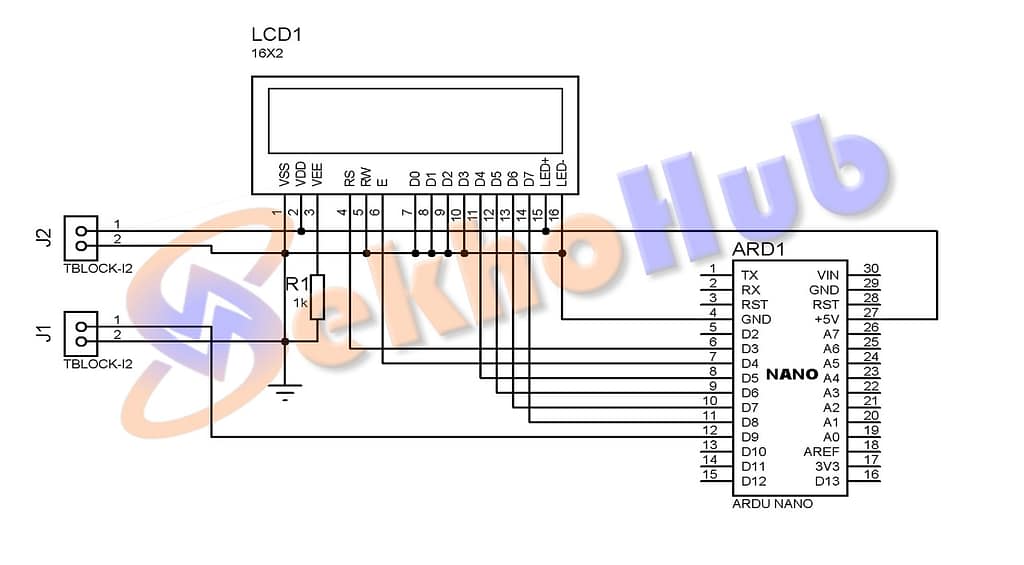
Circuit Diagram Explanation
- Arduino Nano to LCD:
- RS → D3
- E → D4
- D4 → D5
- D5 → D6
- D6 → D7
- D7 → D8
- VCC and GND → Arduino 5V and GND
- Signal Input:
- Signal source → Digital pin D9 (via 1K resistor)
The 1K resistor ensures the input is protected from excess current and helps stabilize the signal.
Step-by-Step Guide
Step 1 – Gather Your Components
Make sure you have an Arduino Nano, a 16×2 LCD, a 1K resistor, a breadboard, and jumper wires.
Step 2 – Connect the LCD to Arduino Nano
Wire the LCD according to the connections above. Use a breadboard to make the layout cleaner.
Step 3 – Connect the Signal Input
Connect your signal generator output to Arduino pin D9 through the 1K resistor.
Step 4 – Upload the Arduino Code
You’ll need the LiquidCrystal library (already included in Arduino IDE). The code counts pulses for one second, then updates the LCD with the frequency.
Step 5 – Test Your Project
Feed in a known signal from a function generator and check if the displayed value matches the expected frequency.
Applications
- Testing oscillators and waveform generators
- Radio frequency projects
- Motor speed measurement via tachometer signals
- Educational lab experiments
FAQs
Q1: Can I measure very high frequencies with this project?
Not directly—Arduino Nano can measure up to a few hundred kHz reliably. For higher frequencies, you’ll need prescaler circuits.
Q2: Do I need an external crystal for accuracy?
Arduino Nano’s internal oscillator is good enough for hobby work, but for precision, use an Arduino with an external 16 MHz crystal.
Q3: Can I display the frequency in kHz or MHz?
Yes—modify the code to divide the result and format the output accordingly.
Q4: Will this work with sine wave signals?
Yes, but you might need a Schmitt trigger circuit to clean up the waveform before feeding it to the Arduino.