
Introduction
Building a DIY 4DOF Robotic Arm is an excellent way to understand how real robotic systems function while gaining hands-on experience with servo control and mechanical assembly.
This project lets you explore essential ideas like robotic arm kinematics, end effector movement, and robot joint angles in a simple, practical format.By combining an Arduino, multiple servos, and a stable link structure, you can create a compact arm capable of controlled motion across four degrees of freedom.
Along the way, you’ll also learn how Arduino PWM control shapes each axis’s behavior, making this build ideal for students, beginners, and makers who want to dive deeper into robotics.
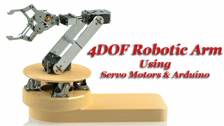
Understanding the 4DOF Structure
A 4DOF robot arm includes four controlled joints:
Base Rotation (DOF 1)
Allows the arm to sweep horizontally around its axis.Shoulder Movement (DOF 2)
Raises or lowers the main arm segment.Elbow Movement (DOF 3)
Extends or retracts the arm’s reach.Wrist/Gripper Control (DOF 4)
Operates the claw or adjusts wrist orientation.
These joints follow simple mechanical principles but require proper torque distribution. Servo motors with decent stall torque ensure smooth robotic arm stability and reliable motion control.

Benefits of This Arduino-based Automation Project
Teaches mechanical robotics basics
Introduces how servo motors move each axis
Helps understand robotic motion control
Offers a complete hands-on STEM robotics project
Easy to expand using joystick modules, sensors, or wireless control
Uses inexpensive and readily available components
Ideal for students and hobbyists
Bill of Materials Components List
| Component | Quantity | Description | Buy Link |
|---|---|---|---|
| Arduino Nano | 1 | Main microcontroller for servo control | Buy Link |
| MG995 / MG996R Servo Motors | 4 | For base, shoulder, elbow, and wrist | Buy Link |
| 10K Potentiometer | 4 | Analog control for each robotic joint | Buy Link |
| 2-Pin Terminal Block | 1 | For external power connection | Buy Link |
| External 5V Power Adapter | 1 | Powers servo motors | Buy Link |
| Jumper Wires | 1 set | Male-to-male, male-to-female | Buy Link |
| Robotic Arm Mechanical Kit | 1 | Acrylic or metal 4DOF structure | Buy Link |
| Breadboard | 1 | For potentiometer connections | Buy Link |
Circuit Diagram Explanation
Below is a simplified breakdown of the Arduino servo control diagram for the 4DOF setup.
Potentiometers → Arduino Analog Pins
Each potentiometer supplies a varying voltage (0–5V), creating an analog value (0–1023).
Pot 1 → A0
Pot 2 → A1
Pot 3 → A2
Pot 4 → A3
One side pin of each potentiometer goes to +5V, the other to GND, and the center wiper goes to the analog input.
Servo Motors → Digital PWM Pins
Each servo motor requires:
+5V
GND
PWM signal
Connections:
Servo 1 (Base Rotation) → D11
Servo 2 (Shoulder Joint) → D10
Servo 3 (Elbow Joint) → D9
Servo 4 (Wrist/Gripper) → D6
Power Notes
Servos draw current quickly under load.
Use a stable 5V external power supply through the terminal block.
Circuit Diagram

Robotic Arm Mechanical Structure
The structural elements follow familiar robotic engineering basics:
Base Plate
Shoulder Bracket
Elbow Link
Wrist Support or Gripper
Using a multi-degree acrylic or aluminum kit ensures better robotic arm stability and smoothness in motion. If designing your own links, apply servo torque calculation to prevent overloading motors.
Step-by-Step Build Guide
Step 1.
First, I’m going to connect the Arduino.
After that, I will connect a two-pin terminal block. One pin goes to the 5V pin of the Arduino, and the other pin goes to GND.
Step 2.
Next, connect a 10K potentiometer.
• One side pin to the positive supply
• The other side pin to ground
• The center pin to the A0 pin of the Arduino
Step 3.
Now connect another 10K potentiometer.
• One side to positive supply
• Other side to ground
• Center pin to A1
Step 4.
Then connect the third 10K potentiometer.
• One side to positive supply
• Other side to ground
• Center pin to A2
Step 5.
Connect the fourth 10K potentiometer in the same way:
• One side to positive supply
• Other side to ground
• Center pin to A3
Step 6.
Now let’s move to the servo motors.
Connect the first servo motor:
• Positive to 5V
• Ground to GND
• Signal pin to D11
Step 7.
Connect the second servo motor:
• Positive to 5V
• Ground to GND
• Signal pin to D10
Step 8.
Connect the third servo motor:
• Positive to 5V
• Ground to GND
• Signal pin to D9
Step 9.
Finally, connect the fourth servo motor:
• Positive to 5V
• Ground to GND
• Signal pin to D6
Step 10.
So now we have completed all the wiring connections.
Let’s upload the code to the Arduino and test the project.
Arduino Code
#include <Servo.h>
Servo myservo; // create servo object to control a servo
Servo myservo1;
Servo myservo2;
Servo myservo3;
int potpin = A0; // analog pin used to connect the potentiometer
int val,val1,val2,val3; // variable to read the value from the analog pinvoid setup() {
Serial.begin(9600);
myservo.attach(6);
myservo1.attach(9);
myservo2.attach(10);
myservo3.attach(11);
// attaches the servo on pin 9 to the servo object
}void loop() {
val = analogRead(A0);
val = map(val, 0, 1023, 0, 30);val1 = analogRead(A1);
val1 = map(val1, 0, 1023, 0, 180);
val2 = analogRead(A2);
val2 = map(val2, 0, 1023, 0, 180);
val3 = analogRead(A3);
val3 = map(val3, 0, 1023, 0, 180);
//delay(100);
// scale it for use with the servo (value between 0 and 180)
myservo.write(val);myservo1.write(val1);
myservo2.write(val2);
myservo3.write(val3);
Serial.print(“v “);
Serial.print(val);
Serial.print(” v1 “);
Serial.print(val1);
Serial.print(” v2 “);
Serial.print(val2);
Serial.print(” v3 “);
Serial.println(val3);
// sets the servo position according to the scaled value
delay(15); // waits for the servo to get there
}
How the Arm Actually Moves
Every time you rotate a potentiometer:
Arduino reads the analog value.
That value maps to a servo angle (0–180°).
PWM output adjusts the servo’s shaft position.
The mechanical structure moves according to the joint’s range.
This represents a basic example of robotic arm programming and forms the basis for more complex forms of robotic arm kinematics and automated operation.
Performance Tips
Keep servo cables short to reduce noise.
Use metal-gear servos for demanding angles.
Maintain lubrication on mechanical joints.
Add counterweights for improved stability.
If using a 3D printed frame, increase infill for strength.
Use Cases of This 4DOF Arm
STEM education
Pick-and-place demonstration
Gesture-controlled robotics extension
Object sorting automation
Research prototyping
DIY automation projects
Remote handling concepts
For more beginner-friendly electronics and robotics projects, explore related categories on SekhoHub.online.
FAQs
What are the 4 D’s of robotics?
The 4 D’s refer to tasks that are Dull, Dirty, Dangerous, and Difficult, which robots are designed to handle more efficiently and safely.
What is a 4 DOF robotic arm?
A 4 DOF robotic arm has four independent axes of motion, typically including base rotation, shoulder lift, elbow movement, and wrist or gripper control.
Can 4D systems be used in robotics?
Yes, 4D systems such as real-time simulation, dynamic modeling, or spatial mapping can be applied to enhance robotic planning and movement accuracy.
What are the big 4 of robotics?
The “big four” usually refer to sensing, movement, manipulation, and control, which form the core functions of robotics technology.
What are the 5 D’s of robotics?
The 5 D’s expand the concept to Dull, Dirty, Dangerous, Difficult, and Dear, meaning tasks that are costly or risky for humans but suitable for robots.