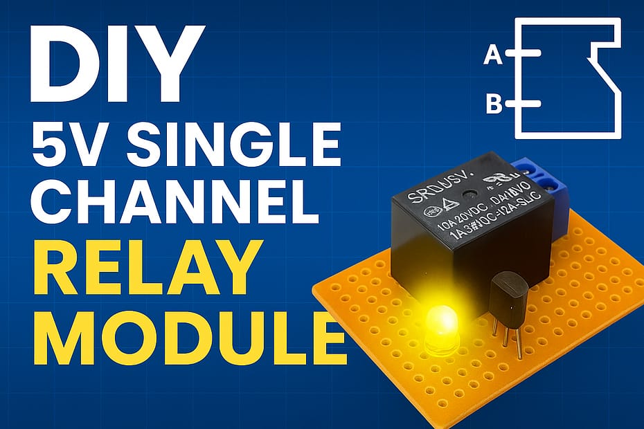
DIY 5V Single Channel Relay Module
[Sekhohub.online]
Here’s a complete guide to building a DIY 5V Single Channel Relay Module—perfect for controlling AC or DC loads using microcontrollers like Arduino, ESP32, or Raspberry Pi.

DIY 5V Single Channel Relay Module
✅What It Does:
Allows low-power devices (like Arduino) to switch ON/OFF high-power loads, such as:
Bulbs
Fans ️
Pumps
Appliances ⚙️
Materials for the Project.
- 1X BC547 TRANSISTOR
- 2X LEDs
- 2X 100 OHM RESISTORS
- 1X 1K RESISTOR
- 1X 5V RELAY
- 1X 2 PIN MALE HEADER
- 1X 3-PIN TERMINAL BLOCK
- PERF BOARD
- JUMPER WIRES
A 1N4007 diode across the relay coil (cathode to +5V)—prevents damage from back EMF.
An LED and a 220Ω resistor in series to ground from the transistor base for indication.
How It Works:
The microcontroller sends a HIGH signal (5V) to the transistor base via a resistor.
The transistor turns ON, allowing current to flow through the relay coil.
The relay activates, connecting COM and NO (normally open)—turning the connected load ON.
Removing the signal turns the relay OFF, disconnecting the load.
Control with Arduino Example
int relayPin = 7;
void setup() {
pinMode(relayPin, OUTPUT);
}
void loop() {
digitalWrite(relayPin, HIGH); // Turns relay ON
delay(1000);
digitalWrite(relayPin, LOW); // Turns relay OFF
delay(1000);
}
⚠️ Safety Tips
NEVER touch relay contacts when connected to AC mains.
Use an optocoupler for safer isolation (optional).
Use heat shrink tubing or a relay module case if permanent.
Video Tutorial
Download Circuit Diagram