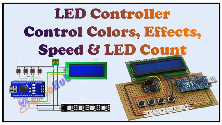
DIY Addressable LED Controller Using Arduino | Control Colors, Effects, Speed & LED Count
This article explains how to make a DIY addressable LED controller using Arduino, WS2812 LEDs, and a 16×2 LCD with buttons. With this addressable LED controller using Arduino, you can change LED colors, adjust speed, select effects, and set the number of LEDs. This project makes an addressable LED controller using Arduino simple for beginners. Whether you are making an addressable LED controller using Arduino for decoration, ambient lighting, or learning, this guide is detailed. Explore step-by-step building of an addressable LED controller using Arduino for your DIY electronics projects.
Introduction
Controlling RGB LEDs is always an exciting DIY project. Unlike ordinary RGB strips, addressable LEDs (like WS2812B or SK6812) allow you to individually control each LED with different colors and animations.
In this project, we’ll design a DIY Addressable LED Controller using Arduino Nano. The controller will let us:
Change LED colors
Select from multiple lighting effects
Adjust animation speed ⚡
Control the number of LEDs
Display settings on a 16×2 LCD with I2C module
Use push buttons for easy navigation
Materials for the Project
| Component | Quantity | Description | Buy Link |
|---|---|---|---|
| Arduino Nano | 1 | Main controller | Arduino Nano |
| WS2812B LED Strip | As required | Individually addressable RGB LED strip | WS2812B Strip |
| 16×2 LCD with I2C | 1 | Display settings and menu | I2C LCD |
| Push Buttons | 4 | Menu, Select, Up, Down | Tactile Switches |
| 330Ω Resistor | 1 | Data line protection | Resistor Kit |
| 1000µF Capacitor (16V) | 1 | Protect LEDs from voltage spikes | Capacitor |
| External 5V Power Supply | 1 | 5V, 3–10A (depending on LED count) | Meanwell 5V Supply |
| PCB or Breadboard | 1 | Circuit assembly | — |
| Jumper Wires | Several | Connections | — |
Useful Tools
| Tool | Quantity | Purpose / Notes | Click & Buy |
|---|---|---|---|
| Soldering Iron Kit | 1 | For making permanent connections | Click & Buy |
| Solder Wire (60/40, 0.8mm) | 1 | Electrical soldering | Click & Buy |
| Wire Stripper & Cutter | 1 | Stripping jumper wires | Click & Buy |
| Mini Screwdriver Set | 1 | For module and relay terminal screws | Click & Buy |
| Multimeter | 1 | Testing voltages and continuity | Click & Buy |
| Hot Glue Gun (optional) | 1 | Securing components in place | Click & Buy |
| Small Pliers | 1 | Holding and bending wires | Click & Buy |
| Heat Shrink Tubing Set | 1 | Insulating exposed wires | Click & Buy |
Download Circuit Diagram

⚡ Circuit Diagram Explanation
The uploaded circuit shows:
Arduino Nano as the controller.
D3 → Data Input of WS2812 LED strip.
A4 (SDA) & A5 (SCL) → I2C LCD.
D4, D5, D6, D7 → Buttons (Menu, Select, Up, Down).
Buttons for Menu Control
Menu: cycles through settings.
Select: confirms the chosen option.
Up/Down: increase or decrease values.
LCD (16×2 with I2C)
Displays current mode, selected effect, speed, and LED count.
Makes the controller fully standalone.
WS2812 LED Strip
Controlled by Arduino Nano through pin D3.
Powered by an external 5V power supply (NOT from Arduino).
GND of Arduino and LED strip are connected together.
Power Protection
330Ω resistor in series with data line → prevents signal spikes.
1000µF capacitor across 5V & GND → prevents power surges when LEDs turn ON.
️ Step-by-Step Guide
Step 1: Assemble the Hardware
Place the Arduino Nano on breadboard/PCB.
Connect WS2812 data line to A0
Connect 16×2 LCD via I2C (A4 → SDA, A5 → SCL).
Wire push buttons to D2, D3, D4, D5 with pull-down resistors or use Arduino’s internal pull-ups.
Connect external 5V power to WS2812 strip.
Step 2: Button Navigation
Menu cycles between options: Color → Effect → Speed → LED Count.
Select confirms option.
Up/Down adjust the values.
Step 3: Integrate LED Effects
Some popular effects:
Rainbow Cycle
Comet / Running Dot
Theater Chase
Solid Color
Random Sparkle
Each effect is displayed on the LCD as you select it.
Step 4: Adjust LED Count
User can set how many LEDs are active.
Useful if you connect a strip longer than you want to light up.
Step 5: Adjust Speed
A delay variable controls animation speed.
Button presses increase or decrease delay.
Step 6: Final Upload & Test
Upload final code with all functions combined.
Connect 5V power supply based on number of LEDs.
Test different menus, speeds, effects.
Arduino Code
Applications
Room decoration lighting
Stage or DJ lighting
Mood lighting projects
Custom holiday lights
Learning embedded programming
❓ FAQs
Q1. Can I use Arduino Uno instead of Nano?
Yes, Uno works fine. Just use the same pins for SDA, SCL, and LED data.
Q2. How many LEDs can I control with this setup?
Limited only by power supply. Arduino can handle hundreds of LEDs; just ensure you have enough 5V current.
Q3. Why use a 330Ω resistor on the data line?
It prevents voltage spikes that can damage the first LED.
Q4. Can I power LEDs directly from Arduino’s 5V pin?
No. Arduino can only provide a few hundred mA. Always use an external 5V supply for LED strips.
Q5. Can I add an IR remote or Bluetooth module later?
Yes, the design is expandable. Just add an IR sensor or HC-05 Bluetooth module for wireless control.


