

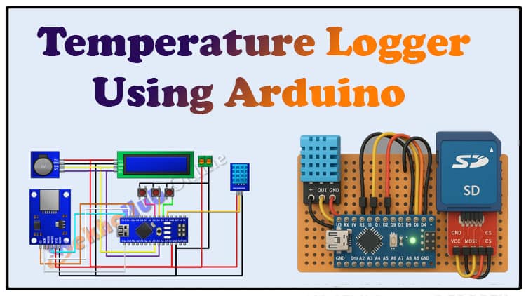
DIY Temperature Logger Using Arduino and SD Card
DIY Temperature Logger Arduino Project is explained step by step in this detailed guide. This DIY Temperature Logger project uses Arduino, a DHT11 sensor, a 16×2 LCD, push buttons, an RTC module, and an SD card module. By following this DIY Temperature Logger tutorial, you can easily build your own temperature monitoring device at home. The DIY Temperature Logger records temperature data in real-time, stores it on an SD card, and displays it on an LCD. With this DIY Temperature Logger, you can track temperature variations accurately.
This DIY Temperature Logger is an excellent project for electronics hobbyists and beginners learning Arduino. The DIY Temperature Logger can be used in weather stations, greenhouses, and labs. Building this DIY Temperature Logger project will enhance your Arduino and data logging skills. Explore the full step-by-step process to complete the DIY Temperature Logger successfully.
Table of Contents
ToggleIntroduction
Hi friends! In this project, we are going to make a DIY Temperature Logger using Arduino. This project will allow us to measure temperature data in real time, display it on an LCD, and log the data onto an SD card for later use.
This kind of project is useful in:
Weather monitoring
Greenhouses
Laboratories
Industrial temperature tracking
Let’s go step by step and build the complete project.
Video Tutorial
Materials for the Project
| S. No | Component | Quantity | Buy Link |
|---|---|---|---|
| 1 | Arduino Nano | 1 | Buy Link |
| 2 | DHT11 Temperature Sensor | 1 | Buy Link |
| 3 | 16×2 LCD Display (I2C Module) | 1 | Buy Link |
| 4 | RTC Module (DS3231 or DS1307) | 1 | Buy Link |
| 5 | SD Card Module | 1 | Buy Link |
| 6 | Push Buttons | 3 | Buy Link |
| 7 | 2 Pin Terminal Block | 1 | Buy Link |
| 8 | Jumper Wires | As Required | Buy Link |
Useful Tools
| Tool | Quantity | Purpose / Notes | Click & Buy |
|---|---|---|---|
| Soldering Iron Kit | 1 | For making permanent connections | Click & Buy |
| Solder Wire (60/40, 0.8mm) | 1 | Electrical soldering | Click & Buy |
| Wire Stripper & Cutter | 1 | Stripping jumper wires | Click & Buy |
| Mini Screwdriver Set | 1 | For module and relay terminal screws | Click & Buy |
| Multimeter | 1 | Testing voltages and continuity | Click & Buy |
| Hot Glue Gun (optional) | 1 | Securing components in place | Click & Buy |
| Small Pliers | 1 | Holding and bending wires | Click & Buy |
| Heat Shrink Tubing Set | 1 | Insulating exposed wires | Click & Buy |
Download Circuit Diagram

Circuit Diagram Explanation
The wiring of the project is straightforward. Let’s break it down:
Arduino Nano is the main controller.
2-Pin Terminal Block is connected to Arduino for power input.
One pin to 5V
Other pin to GND
16×2 LCD with I2C:
VCC → 5V
GND → GND
SDA → A4
SCL → A5
Push Buttons:
Button 1 → D3 → GND
Button 2 → D4 → GND
Button 3 → D5 → GND
DHT11 Temperature Sensor:
VCC → 5V
GND → GND
Data → D2
SD Card Module:
VCC → 5V
GND → GND
CS → D10
MOSI → D11
MISO → D12
SCK → D13
Once all these connections are complete, we can upload the Arduino code and test the project.
Complete Arduino Nano Pinout Table

| Pin | Label | Type | Function / Description |
|---|---|---|---|
| 1 | D1 / TX | Digital I/O | UART Transmit (TX) |
| 2 | D0 / RX | Digital I/O | UART Receive (RX) |
| 3 | RESET | Power | Resets the Arduino Nano |
| 4 | GND | Power | Ground |
| 5 | D2 | Digital I/O | External Interrupt 0, General I/O |
| 6 | D3 | Digital I/O | External Interrupt 1, PWM (OC2B) |
| 7 | D4 | Digital I/O | General I/O |
| 8 | D5 | Digital I/O | PWM (OC0B) |
| 9 | D6 | Digital I/O | PWM (OC0A) |
| 10 | D7 | Digital I/O | General I/O |
| 11 | D8 | Digital I/O | General I/O |
| 12 | D9 | Digital I/O | PWM (OC1A) |
| 13 | D10 | Digital I/O | PWM (OC1B), SPI Chip Select (SS) |
| 14 | D11 / MOSI | Digital I/O | PWM (OC2A), SPI Master Out |
| 15 | D12 / MISO | Digital I/O | SPI Master In |
| 16 | D13 / SCK | Digital I/O | SPI Clock, Onboard LED |
| 17 | 3.3V | Power | 3.3V output (from FTDI chip, ~50mA max) |
| 18 | AREF | Power | Analog Reference for ADC |
| 19 | A0 | Analog Input | ADC Channel 0 |
| 20 | A1 | Analog Input | ADC Channel 1 |
| 21 | A2 | Analog Input | ADC Channel 2 |
| 22 | A3 | Analog Input | ADC Channel 3 |
| 23 | A4 / SDA | Analog I/O | ADC Channel 4, I²C SDA |
| 24 | A5 / SCL | Analog I/O | ADC Channel 5, I²C SCL |
| 25 | A6 | Analog Input | ADC Channel 6 (input only) |
| 26 | A7 | Analog Input | ADC Channel 7 (input only) |
| 27 | 5V | Power | +5V regulated output |
| 28 | RESET | Power | Resets the Arduino Nano |
| 29 | GND | Power | Ground |
| 30 | VIN | Power | Input voltage (7–12V recommended) |
DHT11 Temperature Sensor Pinout Table

| Pin No. | Pin Name | Function |
|---|---|---|
| 1 | VCC | Power supply (3.3V – 5V, typically 5V) |
| 2 | DATA | Serial data output (digital signal to Arduino) |
| 3 | GND | Ground |
Step-by-Step Guide
Step 1: Power Setup
Connect the 2-pin terminal block to Arduino.
One side to 5V, the other to GND.
Step 2: LCD Connection
Attach the 16×2 LCD using the I2C module.
Connect SDA → A4, SCL → A5.
Power it with 5V and GND.
Step 3: Push Buttons
Use three push buttons for menu navigation and control.
Connect one terminal of each to D3, D4, and D5 respectively.
The other terminals go to GND.
Step 4: Sensor Setup
Connect the DHT11 sensor.
Data → D2,VCC → 5V, GND → GND.
Step 5: SD Card Module
Connect the module for logging.
SCK → D13,MISO → D12,MOSI → D11,CS → D10 .
Power it with 5V and GND.
Step 6: Upload the Code
Arduino Code
Write Arduino code to:
Read temperature from DHT11.
Show it on LCD.
Save data to SD card with timestamp.
Upload using Arduino IDE.
Step 7: Testing the Project
Power the setup.
Temperature should appear on the LCD.
Data will be stored on the SD card in a
.txtor.csvfile.You can retrieve the card and analyze the data on your computer.
Applications of DIY Temperature Logger
Weather Stations: For continuous environment monitoring.
Greenhouses: To track and regulate plant conditions.
Server Rooms: To log temperature variations.
Cold Storage: For food and medicine safety.
Home Labs: For learning data logging techniques.
FAQs
Q1: Can I use Arduino Uno instead of Nano?
Yes, Arduino Uno works fine. Just use the same pin mapping.
Q2: How long can the SD card log data?
It depends on the SD card size. Even a 2GB card can store years of temperature data.
Q3: Can I use a different temperature sensor?
Yes, you can use DHT22 for better accuracy or DS18B20 for waterproof measurements.
Q4: Why use RTC with this project?
RTC ensures accurate date and time stamping of logged data.
Q5: Can this be powered with a battery?
Yes, you can use a 9V battery with a regulator, or a Li-ion battery with a charging module.
Conclusion
We have successfully built a DIY Temperature Logger using Arduino, DHT11, LCD, RTC, and an SD card module. This project not only displays real-time temperature but also logs the data for later analysis. It’s a great project for students and electronics hobbyists to understand sensors, data storage, and Arduino programming.