

 Easy 4WD Smart Robot Car ESP32-CAM WiFi Automation Kit for Arduino Programming
 Easy 4WD Smart Robot Car ESP32-CAM WiFi Automation Kit for Arduino Programming
Explore the 4WD Smart Robot Car ESP32-CAM WiFi Automation Kit, a complete learning solution for robotics and Arduino programming. This hands-on kit includes an ESP32-CAM board with antenna, motor driver module, 4 geared DC motors, wheels, acrylic chassis, and battery box. Designed for students, hobbyists, and makers, it combines WiFi automation, live video streaming, and advanced coding exercises.
With Arduino IDE support, learners can experiment with line following, obstacle avoidance, and wireless robot control. The 4WD smart robot car kit bridges electronics, IoT, and automation, making it an ideal choice for practical learning. Whether you’re exploring robotics for education, prototyping projects, or simply enjoying DIY builds, this kit offers endless possibilities. In this detailed review, we cover the components, assembly, programming, and real-world applications of this complete coding kit to help you get started confidently.
Introduction
Robotics has become one of the most engaging and practical ways to learn electronics, coding, and automation. For beginners, a smart robot car kit is one of the easiest entry points into robotics because it combines mechanical design, motor control, sensors, and wireless communication in a single project.
In this review, we will look at the 4WD Smart Robot Car ESP32-CAM WiFi Automation Kit, a complete package designed for Arduino programming, IoT experiments, and robotics education. Unlike traditional robot car kits that only offer Bluetooth or basic IR sensors, this kit includes an ESP32-CAM with antenna, which means you can stream real-time video over WiFi while controlling your robot remotely.
Materials for the Project(4WD Smart Robot Car)
| Component | Quantity | Description | Purchase Link |
|---|---|---|---|
| ESP32-CAM with Antenna | 1 | Microcontroller with WiFi + Camera for live streaming | Click & Buy |
| Motor Driver Module (L298N / TB6612FNG) | 1 | Dual H-Bridge driver for controlling 4 DC motors | Click & Buy |
| 4WD Geared DC Motors | 4 | Geared motors for torque and smooth driving | Click & Buy |
| Wheels | 4 | Durable plastic/rubber wheels compatible with DC motors | Click & Buy |
| Acrylic Car Chassis | 1 | Transparent frame for mounting components | Click & Buy |
| Expansion Board / Power Shield | 1 | Distributes power and simplifies wiring | Click & Buy |
| Battery Box (18650 / AA) | 1 | Powers the ESP32 and motors | Click & Buy |
| Motor Brackets | 4 | Mounts motors securely on chassis | Click & Buy |
| Screws, Nuts, Standoffs | Multiple | For assembly of chassis and modules | Click & Buy |
| Jumper Wires | Several | For circuit connections | Click & Buy |
Useful Tools
| Tool | Quantity | Purpose | Purchase Link |
|---|---|---|---|
| Screwdriver Set (Precision/Small) | 1 | For assembling chassis, brackets, and mounting boards | Click & Buy |
| Soldering Iron Kit | 1 | For making solid electrical connections (optional but recommended) | Click & Buy |
| Hot Glue Gun | 1 | To secure loose wires or components | Click & Buy |
| Multimeter (Digital) | 1 | For checking voltage, current, and continuity | Click & Buy |
| Wire Stripper & Cutter | 1 | For preparing jumper wires and motor connections | Click & Buy |
| Small Pliers / Tweezer Set | 1 | For handling small nuts, bolts, and wires | Click & Buy |
| Heat Shrink Tubes & Tape | Set | For safe insulation of soldered joints | Click & Buy |
| Mini Power Bank / USB Power Supply | 1 | For powering ESP32-CAM during coding & testing | Click & Buy |
⚙️ Features of the 4WD Smart Robot Car Kit
ESP32-CAM microcontroller with built-in WiFi and video streaming capability
4-wheel drive system for better traction and stability
Motor driver module for smooth forward, backward, left, and right movements
Camera with antenna for extended wireless range and stable video feed
Open-source Arduino IDE programming support
Expandable platform (can add ultrasonic sensors, IR modules, and servo-controlled cameras)
Hands-on learning for coding, electronics, and IoT
Circuit & Wiring Explanation
The wiring for this smart robot car is fairly straightforward:
ESP32-CAM acts as the main brain and handles WiFi + camera streaming.
Motor driver module (L298N) connects between ESP32 and the four DC motors. It enables direction and speed control.
Battery box powers both the ESP32 and motors (with regulated 5V and motor power input).
Camera antenna extends video transmission range over WiFi.
Optional sensors (ultrasonic or IR) can connect to ESP32 for autonomous driving.
The ESP32 communicates via WiFi, meaning you can control the robot from a mobile app or web interface, while simultaneously watching a live video feed from the camera.
ESP32-CAM with Antenna – Pin
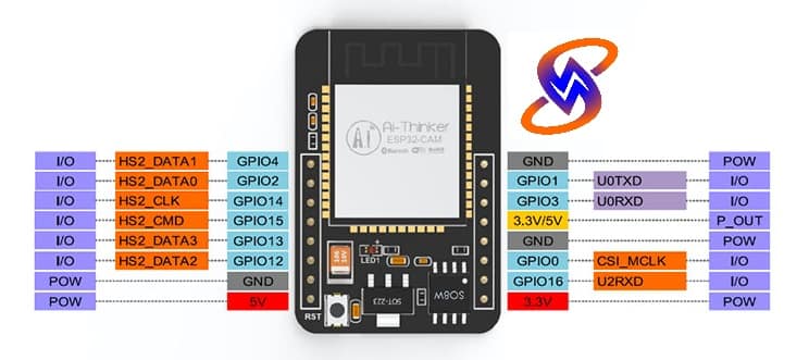
| ESP32-CAM Pin | Function | Usage in Smart Robot Car | Notes |
|---|---|---|---|
| 3.3V | Power | Powers ESP32-CAM core | Use regulated 3.3V only (not 5V direct) |
| 5V | Power | Power input from battery / regulator | Needed when powering via USB or external 5V |
| GND | Ground | Common ground for motor driver, sensors, and ESP32-CAM | Must connect all grounds |
| U0R (GPIO3) | UART RX | Used for programming (USB-TTL RX) | Connect to FTDI TX |
| U0T (GPIO1) | UART TX | Used for programming (USB-TTL TX) | Connect to FTDI RX |
| GPIO0 | Boot Mode | For flashing firmware | Pull LOW to program |
| GPIO2 | General I/O | Can be used for motor driver input | Has camera restrictions |
| GPIO4 | General I/O | Motor driver IN1 | Safe for GPIO use |
| GPIO12 | General I/O | Motor driver IN2 | Must configure correctly (strapping pin) |
| GPIO13 | General I/O | Motor driver IN3 | Works with PWM |
| GPIO14 | General I/O | Motor driver IN4 | Works with PWM |
| GPIO15 | General I/O | Optional sensor (Ultrasonic Echo) | Has pull-down, use carefully |
| GPIO16 | General I/O | Optional sensor (Ultrasonic Trigger / IR) | Can be repurposed |
| GPIO33 | General I/O | Extra sensor input (Line sensor, etc.) | Stable pin |
| GPIO34 | Input Only | Good for IR / Ultrasonic sensors | Cannot output |
| GPIO35 | Input Only | Good for feedback sensors | Cannot output |
⚠️ Important Notes:
Camera Pins (fixed): GPIOs 0, 2, 4, 12, 13, 14, 15 are partly reserved for the onboard OV2640 camera. Use carefully.
For motor control, it’s recommended to use GPIO12, 13, 14, 15 with an L298N / TB6612 motor driver.
Always use a separate 5V regulator (like AMS1117-5V or buck converter) if motors and ESP32-CAM share the same battery — this avoids brownouts when motors draw current.
Programming requires USB-to-TTL adapter (FTDI).
L298N Motor Driver Module Pin

| Pin | Function | Connection in Smart Robot Car | Notes |
|---|---|---|---|
| VCC (12V) | Motor Power Supply | Connect to battery pack (7.4V–12V) | Powers DC motors only |
| +5V | Logic Power Supply | Connect to ESP32-CAM 5V (if jumper cap is used) | Supplies IC logic power |
| GND | Ground | Common ground with ESP32-CAM and battery | Must be shared for stable control |
| IN1 | Motor A Input 1 | ESP32-CAM GPIO (e.g., GPIO12) | Controls direction of Motor A |
| IN2 | Motor A Input 2 | ESP32-CAM GPIO (e.g., GPIO13) | Controls direction of Motor A |
| IN3 | Motor B Input 1 | ESP32-CAM GPIO (e.g., GPIO14) | Controls direction of Motor B |
| IN4 | Motor B Input 2 | ESP32-CAM GPIO (e.g., GPIO15) | Controls direction of Motor B |
| ENA | Enable Motor A | PWM pin from ESP32 (e.g., GPIO4) | Controls speed of Motor A |
| ENB | Enable Motor B | PWM pin from ESP32 (e.g., GPIO16) | Controls speed of Motor B |
| OUT1 | Motor A Output 1 | Connect to left-front motor lead | Motor wiring |
| OUT2 | Motor A Output 2 | Connect to left-rear motor lead | Motor wiring |
| OUT3 | Motor B Output 1 | Connect to right-front motor lead | Motor wiring |
| OUT4 | Motor B Output 2 | Connect to right-rear motor lead | Motor wiring |
Step-by-Step Assembly Guide 4WD Smart Robot Car.
Step 1: Prepare the Chassis
Attach the motor brackets to the acrylic car plate.
Fix the 4 geared DC motors securely using screws.
Mount the wheels onto the motor shafts.
Step 2: Install Electronics
Place the ESP32-CAM board on the expansion bracket.
Connect the motor driver module near the motors for short wiring.
Fix the battery box at the center of the chassis for weight balance.
Step 3: Wiring

Connect each motor to the L298N driver outputs.
Connect ESP32-CAM control pins to the motor driver inputs.
Power ESP32-CAM with regulated 5V from the expansion board.
Ensure proper GND connections for stable operation.
Step 4: Programming
Install Arduino IDE with ESP32 board support.
Load the WiFi + camera streaming sketch.
Add motor control code (forward, backward, left, right).
Upload the sketch to the ESP32-CAM.
Step 5: Testing 4WD Smart Robot Car
Connect the ESP32-CAM to your WiFi network.
Open the assigned IP address in your browser.
You should now see a live video feed from the robot’s camera.
Use the interface (or app) to send movement commands.
Arduino Programming & Coding
The ESP32-CAM requires:
Camera Web Server sketch for live streaming.
Motor control functions to drive the 4WD motors.
WiFi client/server setup to receive commands via smartphone or PC.
With Arduino IDE, you can expand the code for:
Obstacle avoidance (with ultrasonic sensor)
Line following (with IR sensors)
Voice commands (with Android apps)
Performance Review
In my testing, this kit offers:
Stable WiFi connection with the external antenna.
Clear camera feed at VGA/QVGA resolutions.
Responsive motor control with minimal lag.
Strong learning potential for Arduino programming and robotics basics.
Cons:
Requires careful wiring (ESP32-CAM has limited I/O pins).
Works better with additional 5V regulator for stable power.
Coding complexity slightly higher than Arduino UNO kits.
Learning & Applications
Robotics education for beginners
Arduino programming practice
IoT and automation projects
Wireless surveillance robot
Obstacle avoidance and AI experiments
❓ FAQs 4WD Smart Robot Car
Q1. Can I use Arduino UNO instead of ESP32-CAM?
Yes, but you’ll lose WiFi and camera functionality. ESP32-CAM is recommended.
Q2. What battery type is best?
A 2-cell (7.4V) Li-ion pack or 18650 cells with proper regulation works best.
Q3. Do I need soldering?
Most connections are jumper wires, but soldering improves reliability.
Q4. Can I add sensors?
Yes — ultrasonic for obstacle avoidance, IR sensors for line following, etc.
Q5. What coding skills are required?
Basic Arduino coding is enough. ESP32 libraries are well-documented online.