
Introduction.
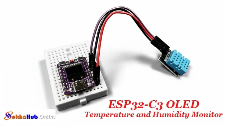
The ESP32-C3 OLED Temperature and Humidity Monitor Using DHT11 is a compact, practical setup designed for enthusiasts who want to measure indoor conditions with a reliable microcontroller. This build uses the onboard OLED to present live environmental values, making the project both educational and functional.
The DHT11 enables basic sensing of room conditions, while the ESP32-C3 handles data processing and display output smoothly. With its simple wiring and beginner-friendly workflow, the system becomes a great way to learn about embedded devices, sensor modules, and real-time data visualization. Whether for study or experimentation, it offers a clear path into environmental monitoring and DIY electronics.
Project Overview
This project demonstrates how an ESP32-C3 board with a built-in OLED display can be turned into a compact temperature and humidity monitoring system using the DHT11 sensor. The goal is to build a small monitor capable of showing readings in real time, making it suitable for tutorials, learning exercises, and practical DIY electronics experimentation.
The microcontroller communicates with the DHT11 through a single GPIO line, while the onboard OLED operates through the I2C interface. With only a few components, the design becomes an excellent project for beginners working with Arduino, ESP-IDF, or small module-based circuits. The design also reflects typical requirements in embedded electronics projects, including data acquisition, accuracy, calibration, and real-world environmental sensing.
How It Works
The DHT11 measures temperature and humidity using its internal digital sensing module. It sends data packets using the DHT11 timing protocol, which includes start pulses, response phases, and checksum verification. The ESP32-C3 captures these pulses through GPIO2, decodes the binary values, and displays the readings on the onboard OLED via the I2C bus.
The compact board simplifies the setup, making the design ideal for a microcontroller-based weather station, environmental monitoring system, or small ESP32-C3 project. The display driver uses the SSD1306 OLED library, drawing text, icons, and numerical values with minimal overhead.
ESP32-C3 OLED Temperature and Humidity Monitor
This section highlights how the complete ESP32-C3 OLED temperature monitor works as a practical tool for indoor climate observation. It delivers real-time metrics, enabling the development of an embedded electronics project for homes, laboratories, or classrooms.
Components Required
Wiring Connections
DHT11 → ESP32-C3
| DHT11 Pin | ESP32-C3 Pin | Description |
|---|---|---|
| VCC | 3.3V | Power supply |
| GND | GND | Ground |
| DATA | GPIO2 | Sensor data pin |
The 0.42-inch OLED integrated on the ESP32-C3 module operates on the I2C protocol:

| OLED Pin | GPIO | Function |
|---|---|---|
| SDA | 5 | I²C data |
| SCL | 6 | I²C clock |
These pins are fixed on most ESP32-C3 boards with onboard displays.
dht11 – 3-pin module version

Libraries Required
Install these through Arduino IDE:
U8g2 by olikraus (for OLED display)
DHT sensor library by Adafruit
Adafruit Unified Sensor (dependency)
These libraries simplify I2C OLED communication, sensor parsing, and ensure stable readings during continuous updates.
Circuit Diagram Explanation

The circuit is simple because both primary components—the OLED and DHT11—rely on built-in pin configurations.
The I2C OLED connection uses SDA and SCL, pre-wired on the ESP32-C3 module.
The DHT11 sensor module connects through a single GPIO line.
The data acquisition circuit processes the digital packets from the DHT11 and sends them to the microcontroller.
Because the design runs at 3.3V, no level shifting is needed. This also supports a low-power IoT design, perfect for battery-based prototypes.
Step-by-Step Build Guide
Step 1.
Place the ESP32-C3 board onto a breadboard if you plan to prototype.
Step 2.
Connect the DHT11 VCC pin to 3.3V on the ESP32-C3.
Step 3.
Connect the GND pin of the sensor to the ESP32-C3 GND.
Step 4.
Now connect the DATA pin of the DHT11 to GPIO2 of the microcontroller.
Step 5.
Verify that the onboard OLED is functional by running a basic example from the U8g2 Library.
Step 6.
Install the DHT library and the Adafruit Unified Sensor library from the Arduino IDE.
Step 7.
Add the provided Arduino code example into your sketch.
Step 8.
Upload the firmware to the ESP32-C3 using the correct COM port.
Step 9.
Observe the temperature and humidity readings updating on the OLED temperature display.
Step 10.
Make adjustments for better calibration or accuracy if needed.
Arduino Code for ESP32-C3 OLED
This code supports stable real-time sensor update, digital parsing, and OLED display interface without extra libraries.
Applications
DIY sensor project
Weather monitoring system
Home automation temperature control
Indoor climate monitoring
Digital sensor integration coursework
Environmental monitoring system prototypes
This design forms a great starting point for logs, graphs, wireless dashboards, or advanced enhancements like WiFi dashboards or data logging.
FAQs
1. What is the temperature range of ESP32-S3?
ESP32-S3 typically operates from –40°C to +85°C, suitable for industrial environments.
2. What is the normal temperature for ESP32?
Most ESP32 chips normally run between 40°C and 65°C depending on load, WiFi use, and ambient conditions.
3. What are the ESP32-C3 specifications?
ESP32-C3 features a RISC-V core, WiFi + Bluetooth LE, 22 GPIOs, UART/I2C/SPI peripherals, low-power modes, and secure boot support.
4. Can ESP32 overheat?
Yes, ESP32 can overheat if heavily loaded, enclosed without ventilation, or supplied with incorrect voltage.
5. Can ESP32 handle 7.4 V?
No, ESP32 cannot be powered directly with 7.4V; you must regulate it to 5V or 3.3V first.
6. What is the operating temperature of ESP?
Most ESP32 series modules operate within –40°C to +85°C, depending on the specific model.
Conclusion
This guide shows how easily an ESP32-C3 and DHT11 can form a compact temperature and humidity display on OLED, providing a versatile platform for learning, experimenting, or developing small indoor sensing applications. The design integrates digital sensing, I2C communication, and a simple interface, making it an excellent foundation for future enhancements.