

Hart LED Flasher Circuit Using 555 Timer IC
[Sekhohub.online]
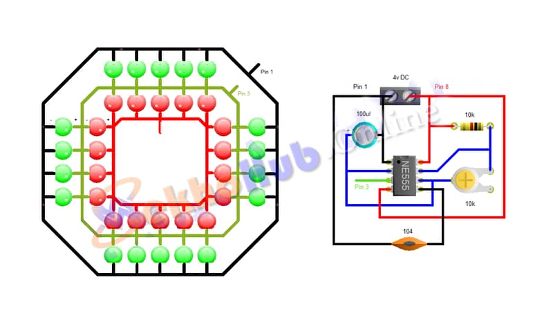
Want to make an LED blink automatically at regular intervals? Using the popular NE555 timer IC, you can easily build a reliable and adjustable LED flasher with just a few components!

Materials for the Project
1. 10k resistor ×1
2. 100uf 50v capacitor ×1
3. 10k variable resistor ×1
4. 104 Ceramic capacitor ×1
5. NE555 ic ×1
6. 5mm Red led ×18
7. 5mm Green led ×18
8. 5 mm LED × 100
9. Brass Wire ×1
How It Works
The 555 timer is configured in astable mode, which means it repeatedly turns ON and OFF, creating a square wave signal. This drives the LED to blink on and off at a frequency determined by two resistors (R1, R2) and a capacitor (C1).
Pinout Reference (555 Timer IC)
| Pin | Name | Function |
|---|---|---|
| 1 | GND | Ground |
| 2 | Trigger | Starts timing cycle |
| 3 | Output | Drives LED |
| 4 | Reset | Active low (tie to Vcc) |
| 5 | Control | Optional (tie to GND via 10 nF) |
| 6 | Threshold | Ends timing cycle |
| 7 | Discharge | Discharges C1 to restart cycle |
| 8 | Vcc | Power Supply (5V) |
Download Circuit Diagram
Final Thoughts
The LED flasher using a 555 timer is a fantastic starter project that helps you understand timing, pulses, and circuit behavior. With just a few resistors and a capacitor, you can make lights blink, buzzers beep, and open the door to automation projects.