
This detailed guide explains the HMI Timer Relay Arduino project covering the working principle, HMI Timer Relay circuit diagram, components list, and setup steps. Learn how to use an HMI display with an Arduino to build an automatic timer relay for industrial automation or DIY control projects. Perfect for students and professionals interested in practical PLC connection and timer-based automation.

Introduction
In the world of automation and industrial control, combining an HMI, Arduino, and relay can create a smart system that automates devices with precision timing. The HMI Timer Relay Arduino project demonstrates how a user-friendly touchscreen interface can manage a digital relay controller, allowing timed switching for various applications like motors, lights, and pumps.
This project provides an educational yet technically rich explanation of how to design and build an HMI based timer relay project that integrates both hardware and software for smooth operation.
Visit SekhoHub.online for more automation and DIY electronics tutorials.
Understanding the HMI Timer Relay Arduino System
An HMI Timer Relay Arduino system merges a touchscreen HMI display with an Arduino microcontroller that controls a relay module through programmed timing logic.
The HMI (Human-Machine Interface) allows users to input timer values using its digital interface. Once the timer value is set, the Arduino counts the duration and triggers the relay output, which in turn switches an external load (like a motor or lamp).
Working Principle of the HMI Timer Relay Arduino
The HMI Timer Relay working principle revolves around user interaction through the HMI display. The display communicates timer values to the Arduino via serial communication.
When the timer starts:
The Arduino begins the countdown.
Once the delay time is completed, the relay output is activated.
After the defined interval, the Arduino resets or waits for the next command.
This makes the circuit suitable for industrial automation where timer control and PLC connection functions are required.
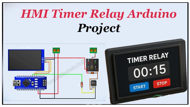
HMI Timer Relay Circuit Diagram
Below is the connection overview for the HMI Timer Relay circuit diagram.

The circuit connects the HMI module, Arduino, BC547 transistor, and 5V relay in a simple control configuration.
HMI Display TX → Arduino D2
HMI Display RX → Arduino D3
Relay driver via BC547 transistor (controlled by D4)
1N4148 diode used across relay coil for back-EMF protection
5V supply shared between HMI module and Arduino
Bill of Materials
| No | Component | Specification | Quantity | Buy Link |
|---|---|---|---|---|
| 1 | Arduino Nano | 5V microcontroller board | 1 | Buy on AliExpress |
| 2 | HMI Display | 2.8”–3.5” Touchscreen HMI module | 1 | Buy on AliExpress |
| 3 | Relay Module | 5V single-channel | 1 | Buy on AliExpress |
| 4 | BC547 Transistor | NPN transistor | 1 | Buy on AliExpress |
| 5 | 1KΩ Resistor | ¼ Watt | 1 | Buy on AliExpress |
| 6 | 1N4148 Diode | Signal diode | 1 | Buy on AliExpress |
| 7 | Terminal Blocks | 2-pin | 2 | Buy on AliExpress |
| 8 | Jumper Wires | Male-to-female | As needed | Buy on AliExpress |
Circuit Explanation
The HMI Timer Relay Arduino project is powered by a 5V supply shared across the components.
The HMI interface sends serial data to the Arduino, which interprets the timer value.
The Arduino controls a relay driver circuit consisting of:
BC547 transistor as the switching device.
1K resistor limiting base current.
1N4148 diode preventing reverse current damage.
When the HMI timer triggers, the Arduino outputs a HIGH signal on D4, turning the transistor ON, which energizes the relay coil.
The relay output can then control AC or DC devices safely.
This digital timer control system can be expanded for PLC connection or integrated with industrial control panels.
Step-by-Step Build Guide
Step 1. Prepare all components
Gather the components listed in the BOM. Make sure your Arduino, HMI display, and relay module are compatible (5V logic level).
Step 2. Connect power terminals
Connect the Arduino 5V to the VCC of the HMI and relay module.
Join all grounds (GND) together to form a common reference.
Step 3. Connect the HMI module
Connect TX of the HMI to D2 of the Arduino, and RX of the HMI to D3 of the Arduino.
This serial connection allows real-time communication between the HMI interface and Arduino.
Step 4. Build the relay driver circuit
Connect the BC547 transistor emitter to GND.
Connect its collector to one coil terminal of the relay.
The other relay coil terminal connects to 5V.
Use a 1K resistor from Arduino D4 to the transistor base.
Place a 1N4148 diode across the relay coil for protection.
Step 5. Connect the relay output terminal block
Connect one terminal to the NO (Normally Open) contact and the other to the COM (Common) contact.
This allows you to connect external loads later.
Step 6. Upload the Arduino code
#include <SoftwareSerial.h>
String dat;
SoftwareSerial mySerial(3, 2); // RX 3, TX 4
char ch;
unsigned int tmr,tmr1;
uint8_t fx,fx1;
bool t1;
void setup() {
pinMode(4, OUTPUT);mySerial.begin(9600);
Serial.begin(9600);
}void loop() { // run over and over
while (mySerial.available()) {dat=mySerial.readString();
ch=dat[0];fx=dat[1];
fx1=dat[2];
if(t1&(fx+fx1)>0){t1=0;tmr=0;}
else {t1=1;tmr=fx+fx1*256;}}
if(t1)tmr1++;
if(t1){ writeHMI(“st.txt=\”STOP\””);digitalWrite(4,1);writeHMI(“t2.txt=\”ON\””);}
else{writeHMI(“t2.txt=\”OFF\””); digitalWrite(4,0);writeHMI(“st.txt=\”START\””);}
if(tmr1>=tmr)t1=tmr1=0;
sendHMI(“n0.val=”,tmr1);
delay(1000);
}
void sendHMI(String cmd,long num){
mySerial.print(cmd);
mySerial.print(num);
mySerial.write(0xff);
mySerial.write(0xff);
mySerial.write(0xff);}
void writeHMI(String cmd){
mySerial.print(cmd);
mySerial.write(0xff);
mySerial.write(0xff);
mySerial.write(0xff);}
Load the HMI communication sketch into Arduino IDE.
Ensure the code includes serial commands to receive the timer value and control relay activation.
Step 7. Test the system
Power on the circuit.
Set a timer value on the HMI display using the touchscreen interface.
Observe how the relay output activates after the defined delay period.
Step 8. Fine-tune and deploy
You can adjust delay times, add more relays, or link this to a PLC for enhanced industrial automation.
How HMI Timer Relay Works
When the user enters a time delay using the HMI touchscreen interface, the data is transmitted to the Arduino’s serial pins.
The Arduino starts a countdown and activates the relay module after the set interval.
Once triggered, the relay output connects power to the load.
This operation replicates a digital timer relay system used in industrial automation and can be customized for various timing and PLC connection tasks.
Applications
The HMI Timer Relay Arduino project is versatile and practical.
It can be used for:
Industrial automation tutorial demonstrations
DIY HMI timer relay project experiments
PLC timer circuit integration
Automatic timer relay with HMI display systems
Touchscreen control panel prototypes
Time delay relay applications in lighting or motor control
Electrical automation projects and student learning setups
Advantages
Easy to operate via digital touchscreen interface
Provides precise timer control
Can be integrated with PLC systems
Modular and expandable for multi-relay configurations
Cost-effective for industrial and DIY automation tasks
Safety and Precautions
Always power the circuit with a regulated 5V DC supply.
Do not connect AC loads directly without using relay isolation.
Avoid overloading the relay module beyond its rated current.
Double-check wiring before powering on the HMI display.
Further Expansion
For advanced users, the same HMI Timer Relay Arduino circuit can be expanded by:
Adding multiple relays for multi-channel automation control.
Connecting the system to a PLC for industrial-grade logic control.
Logging timing data through serial monitoring for digital relay controller applications.
Designing a touchscreen control panel layout with adjustable modes.
You can explore similar HMI-based automation tutorials at SekhoHub.online.
FAQs about HMI Timer Relay Arduino
Q1. What is the purpose of an HMI Timer Relay Arduino project?
It automates device switching by combining an HMI display and Arduino to control a relay module based on user-defined timing.
Q2. Can this project be used in industrial automation?
Yes. The system supports industrial environments and can communicate with PLC connections or operate standalone as a digital relay controller.
Q3. How is the delay controlled?
The delay is set via the HMI interface, transmitted to the Arduino, which then activates the relay output after the specified delay time.
Q4. Is it safe to control AC loads?
Yes, if the relay is rated properly and isolation is ensured. The relay module allows switching of AC or DC loads safely.
Q5. Can I expand this project?
Absolutely. The HMI Timer Relay Arduino can be expanded with additional modules, sensors, or integrated with PLC timer circuits for more complex automation setups.
Conclusion
The HMI Timer Relay Arduino project demonstrates how simple components can create a professional-grade automation system.
By combining an HMI display, relay, and Arduino, users can achieve flexible timer control and seamless interface operation for both industrial and DIY use cases.
This project bridges the gap between digital innovation and practical automation, empowering engineers and hobbyists to build reliable timing systems.